Ce travail est divisé en deux parties : un diviseur de tension reçoit la tension, puis le réduit à un niveau de tension de manière appropriée.
Pour envoyer une entrée à la deuxième partie qui est la partie principale de l'affichage lui-même.
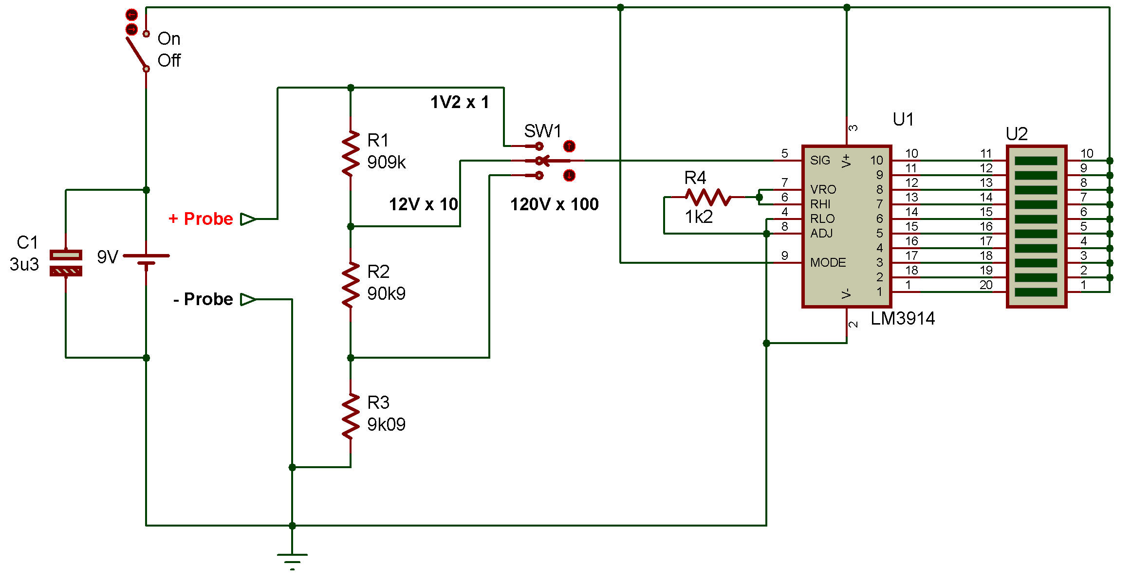
À partir du circuit R1, R2, R3 agit comme divisant la tension au contact de la sonde sur 3 niveaux.
Il y a un interrupteur S2 pour sélectionner la plage de mesure.
Les éléments qui peuvent mesurer la tension dans la troisième plage sont :
Si S2 et sur X1, la tension sera mesurée dans la plage 0-1,2 V.
Si S2 est en position, X10 mesurera la tension dans la plage de 0 à 12 V.
Mais si S1 est le X100 peut être mesuré sur une échelle
égal à 120V.
Which work is divided into two parts: a voltage divider receives the voltage, then reduce a level voltage appropriately.
To send input to the second part which is the main part of the display itself.
From the circuit R1, R2, R3 acts as dividing the voltage at probe touch in a 3 level.
By there is a switch S2 to select the measurement range.
Which can measure the voltage at the third range are: On S2 is at the X1 will measure the voltage in the range 0-1.2V.
If S2 is in position X10 will measure the voltage in the range of 0-12V.
But if S1 is the X100 can be measured on a scale
equal to 120V.
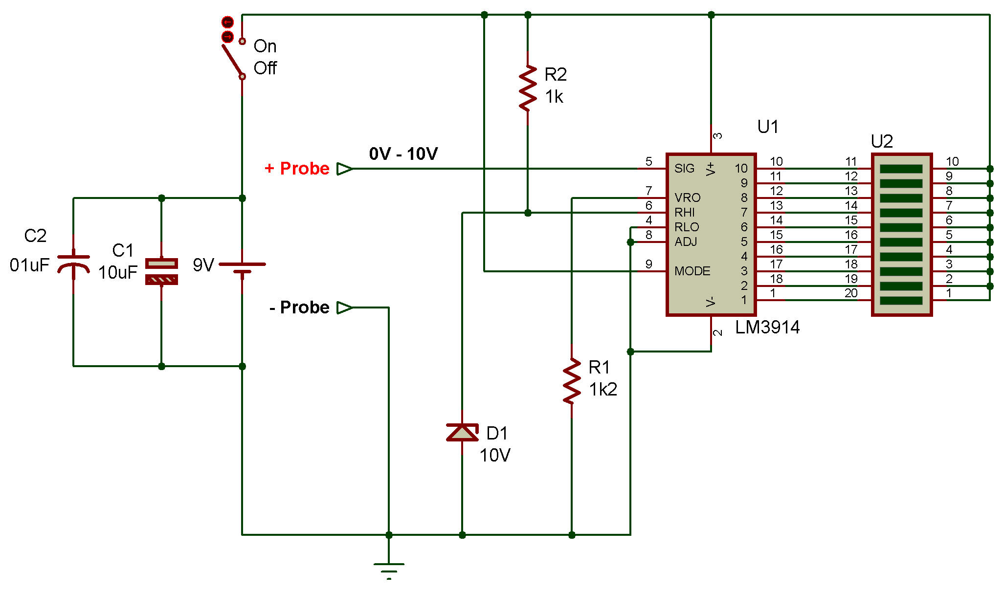
Si la tension de référence est de 1,2 V, si la tension à la broche 5 est égale ou proche de 0,36 Volt à LED3.
Si la tension est de 1,2 V, la LED10 est allumée, ce point est également indiqué.
Broche de tension à pleine échelle 5, elle obtiendra donc une tension de 0 à 1,2 V par R1, R2, R3 et réduira la tension de la sonde elle-même. Pour que la tension à la broche 5 ne dépasse pas 1,2V.
Chaque broche de sortie peut piloter des courants jusqu'à 30 mA et le courant traversant chaque LED peut être contrôlé en utilisant un R4 de 1,2 K ohm, ici le courant sortant de la broche 7 est approximativement égal à 1 mA.
Donc le courant traversant chaque LED est d'environ 10 mA ou environ 10 fois le courant à la broche 7, R4 sert à contrôler la luminosité de la LED et fait également une tension de référence entre les broches 7 et 8 à 1,2 volts.
If the reference voltage is 1.2V if the voltage at pin 5 is equal or close to 0.36 Volt to LED3.
If the voltage is 1.2V LED10 is lit, it is also shown that point.
Full-scale voltage pin 5, so it will get from 0-1.2V voltage by R1, R2, R3 reduce the voltage to the probe handle itself. So that the voltage at pin 5 does not exceed 1.2V.
Each output pin can drive currents up to 30 mA and the current through each LED can be controlled by using a 1.2K ohm R4 here is the current flowing out of pin 7 is approximately equal to 1 mA.
So the current through each LED is around 10 mA or about 10 times the current at pin 7, R4 is to control the brightness of the LED also makes reference voltage between Pin 7 and 8 at 1.2 volts.