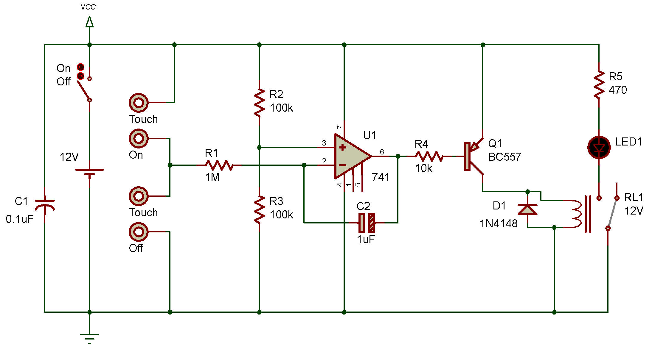
Il s'agit d'un simple circuit d'interrupteur marche/arrêt.
Il a une partie comparable au groupe de tension 2.
Comment ça fonctionne
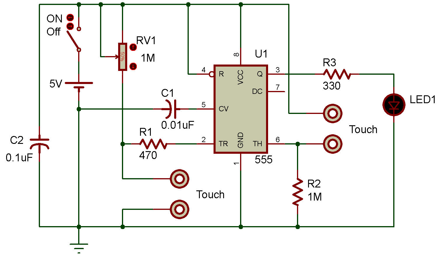
Il y a 2 pavés tactiles pour allumer et éteindre afin de détecter le changement de tension.
Quand on touche le premier touchpad entre la broche 2 et la masse. Notre doigt a une résistance.
Ainsi, il transmet le courant (Hi) à la masse.
Ensuite, à la broche 2 se trouve la logique basse (GND).
Cela provoque l'exécution de l'IC-555.
Ensuite, la haute tension sort de la broche 3 (la sortie).
Après cela, nous touchons le pavé tactile entre la broche 6 et la tension d'alimentation.
Le courant passe par notre doigt jusqu'à la broche 6. La logique passe en basse tension.
De plus, la sortie passe à Low.
Nous pouvons appliquer la sortie pour contrôler d'autres circuits comme les LED, les relais et le circuit d'entrée.
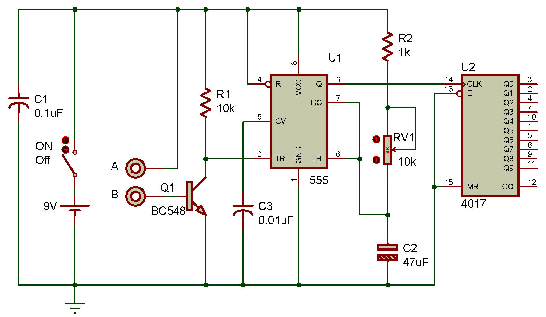
This is a simple touch on and off switch circuit.
It has a part compares with voltage 2 group.
How it works
There are 2 touchpads for turn on and turn off to detect the change of voltage.
When we touch the first touchpad between pin 2 and ground. Our finger has resistance.
So, it passes the current (Hi) to ground.
Then, at pin 2 is Low logic (GND).
It causes the IC-555 runs.
Next, the high voltage goes out of pin 3 (the output).
After that, we touch off the touchpad is between pin 6 and a power supply voltage.
The current flows through our finger to pin6. The logic changes to low voltage.
Also, the output switches to Low.
We can apply the output to control other circuits like LED, relay and input circuit.
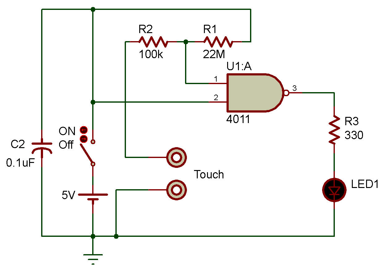
utilisant la porte NAND (NON-ET)
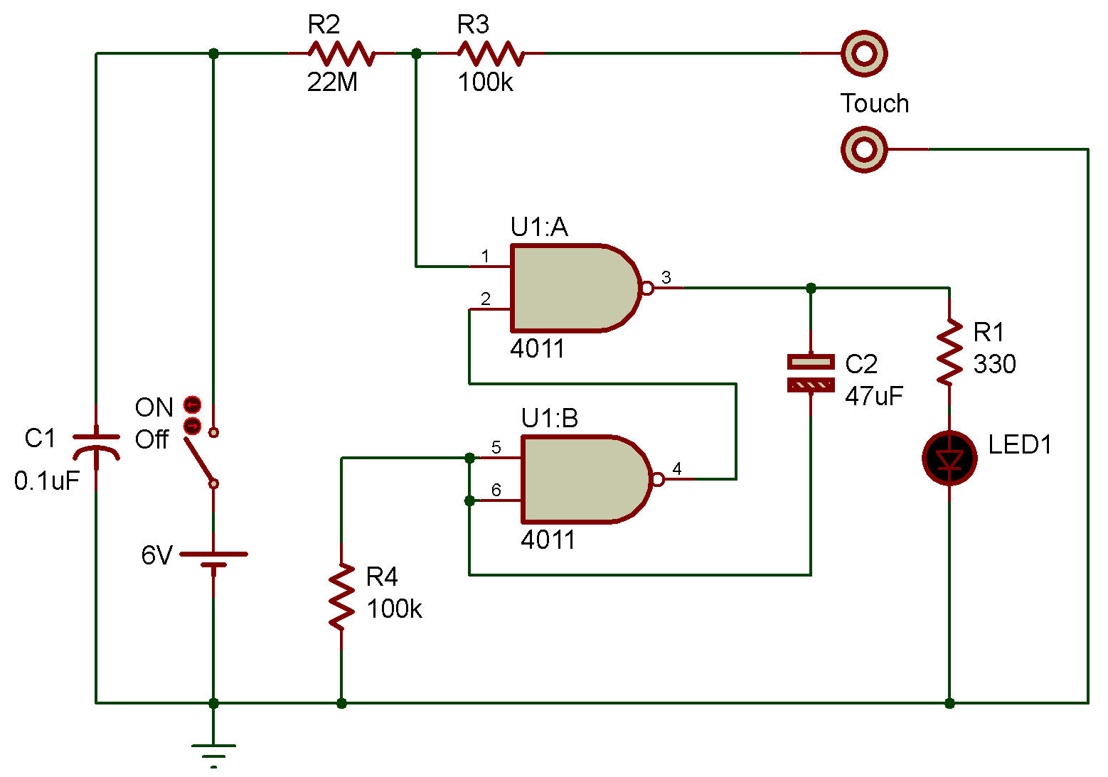
Ce circuit utilise une porte logique numérique 4011 comme base de l'interrupteur tactile.
C'est standard et très simple car
J'ai utilisé une porte d'IC 4011.
La broche 2 du 1/4 IC est à la logique Hi « HI ».
Si vous touchez la plaque connectée au numéro 2.
La sortie logique est donc Hi, mais ne pas la toucher la logique est Low.
La résistance de 22 M sur la broche 1 rend le circuit très sensible au toucher.
This circuit uses a 4011 logic gate digital as the bases of the touch switch.
It is Standard and very easy because
I used a Gate of IC 4011.
Pin 2 of 1/4 IC is Hi logic “HI” away.
If touching the plate connected to the 2 number.
So the logic output is Hi, but don’t touch is Low logic.
The 22M resistor on pin 1 causes the circuit to be very sensitive to the touch.
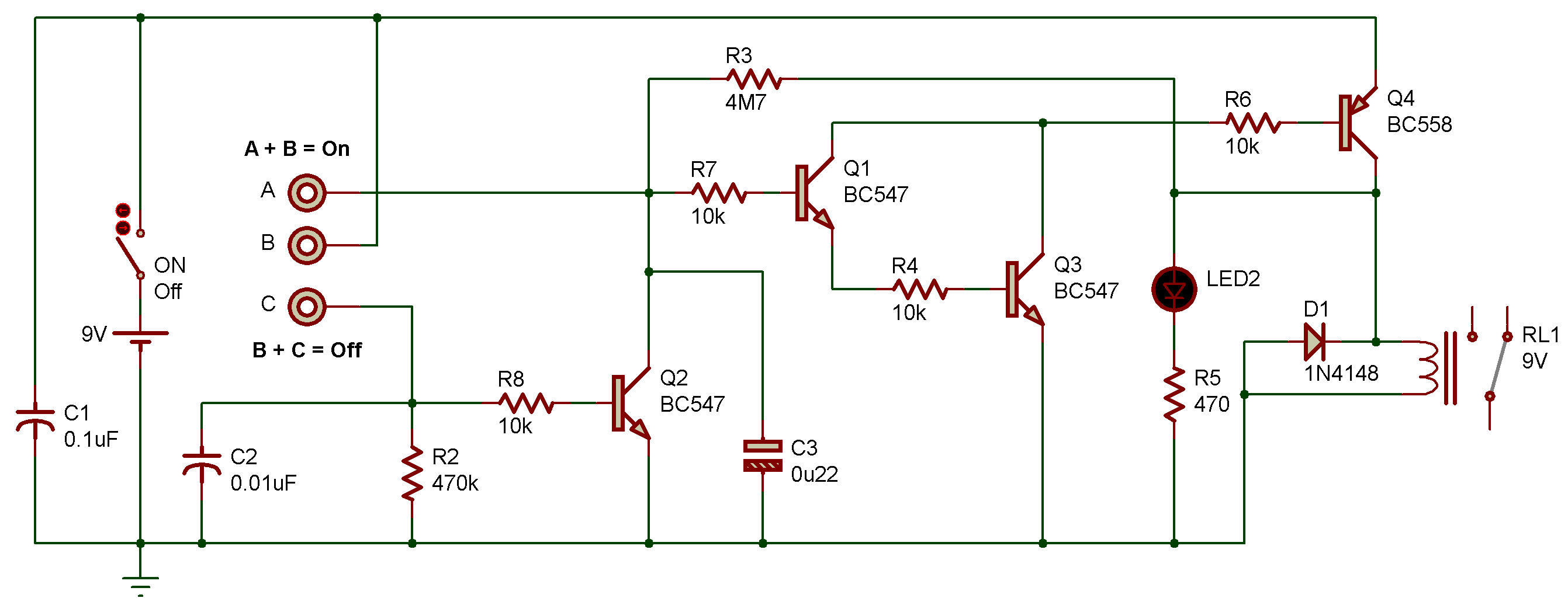
J'utilise le CMOS numérique IC-4011 qui est la base d'un circuit.
Il a la forme d'un flip-flops.
Lorsque votre doigt touche le pavé la logique à une sortie est « HI » et il y a un délai de 3 secondes.
Nous pouvons déterminer ce délai d'impulsion (one-shot) en utilisant le condensateur électrolytique C2 de 47uF (microfarad).
Après avoir touché la plaque connectée, il y a une sortie d'impulsion.
I use IC-4011 digital CMOS is base of a circuit.
It is set to form as flip-flops.
The Logic “HI” at an output when Your finger touchpad and is a time delay for 3 seconds.
Which we can determine this pulse time delay (one-shot) using the C2-electrolytic capacitor of 47uF (microfarad).
After that touching the plate connected, so well pulse output.