
Formulas and Laws Part 2
see also Formulas and Laws Part 1
REACTANCE FORMULAS
The opposition to the flow of alternating current by the inductance or capacitance of a component or circuit is called the reactance. Capacitive Reactance The reactance of a capacitor may be calculated by the formula:

where, Xc is the reactance in ohms, f is the frequency in hertz, C is the capacitance in farads.
Inductive Reactance
The reactance of an inductor may be calculated by the formula:

where, XL is the reactance in ohms, f is the frequency in hertz, L is the inductance in henrys.
RESONANCE FORMULA
The resonant frequency, or the frequency at which the reactances of the circuit add up to zero (XL= Xc), is determined by the formula:

where, fR is the resonant frequency in hertz, L is the inductance in henrys, C is the capacitance in farads.
REACTANCE AND RESONANCE CHARTS
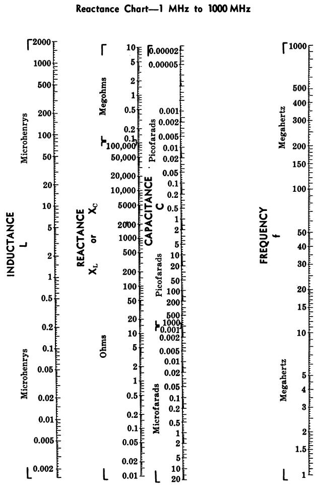
Charts for determining unknown values of reactance, inductance, capacitance, and frequency are given in Figs. 23A, 23B, and 23C.
To find the reactance of a capacitor at a given frequency, lay the straightedge across the capacitor value and the frequency.
Then read the reactance from the reactance scale.
By extending the line, the value of an inductance which will give the same reactance can be obtained.
Since XC = XL at resonance, by laying the straightedge across the capacitance and inductance values, the resonant frequency of the combination can be determined.
Fig. 23A
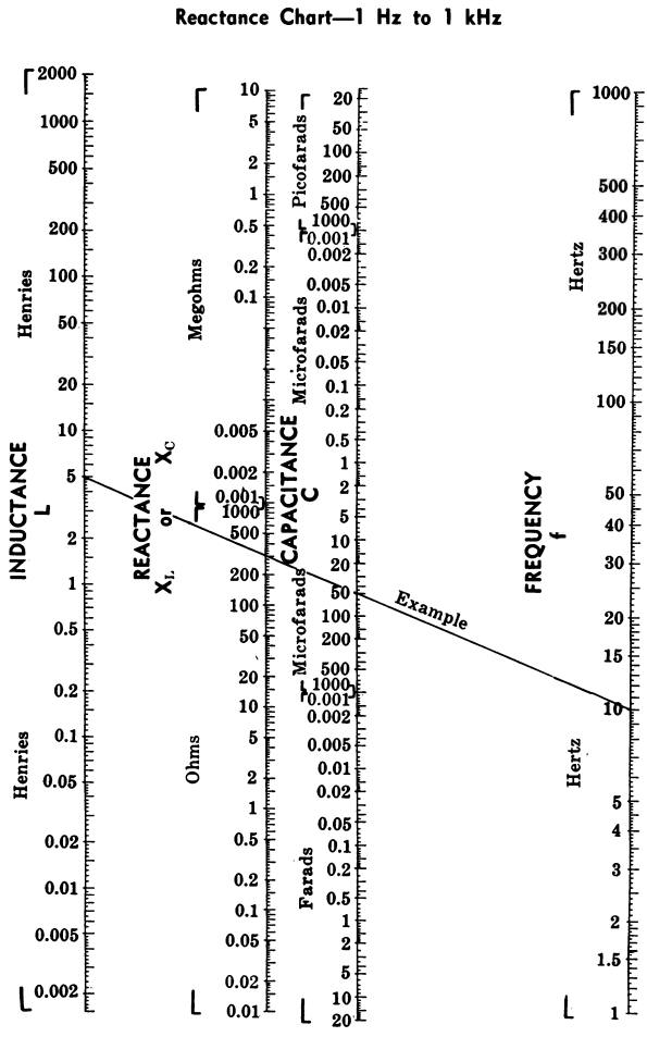
Fig. 23B
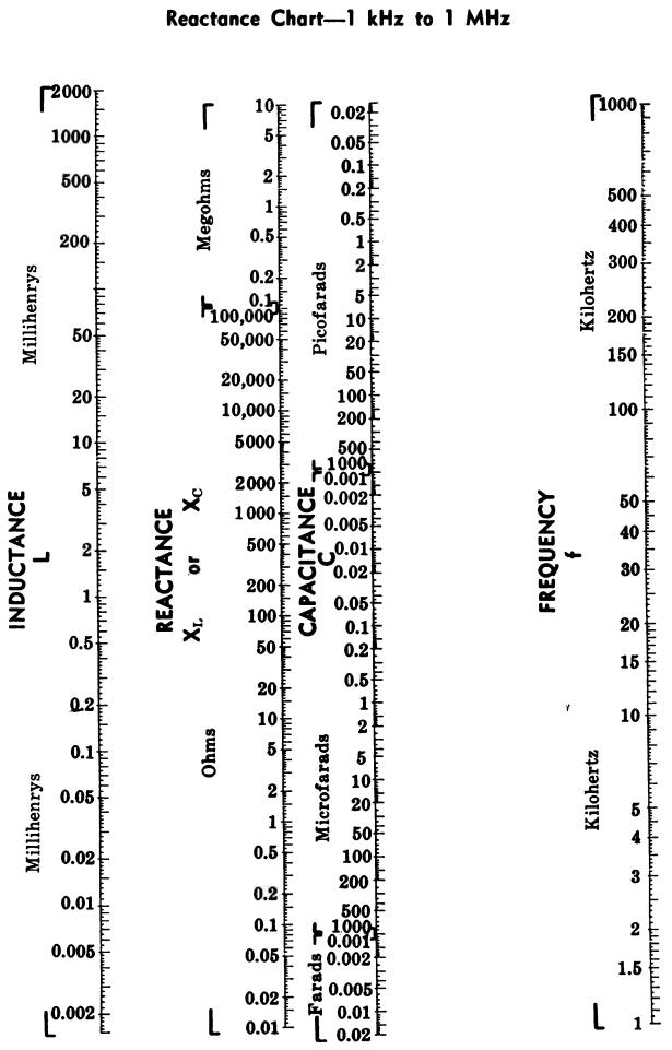
Fig. 23C
Example
If the frequency is 10 hertz and the capacitance is 50 µF, what is the reactance of the capacitor?
What value of inductance will give this same reactance?
Answer
The reactance is 310 ohms. The inductance needed to produce this same reactance is 5 henrys. Thus, it follows that a 50µF capacitor and a 5-henry choke are resonant at 10 hertz.
Place the straightedge, on the proper chart (Fig. 23A), across 10 hertz and 50 µF. Read the values indicated on the reactance and inductance scales.
IMPEDANCE FORMULAS
The basic formulas for calculating the total impedance are as follows.
Parallel circuits

Series circuits

where, Z is the total impedance, G is the total conductance or the reciprocal of the total parallel resistance, : B is the total susceptancee, R is the total resistance, X is the total reactance.
The following formulas can be used to find the impedance of the various combinations of inductance, capacitance, and resistance.
A single resistance (Fig. 24)
Fig. 24

Resistances in series (Fig. 25)
Fig. 25

A single inductance (Fig. 26)
Fig. 26

Inductances in series (with no mutual inductance) (Fig. 27)
Fig. 27

single capacitance (Fig. 28)
Fig. 28

Capacitances in series (Fig. 29)
Fig. 29

Resistance and inductance in series (Fig. 30)
Fig. 30

Resistance and capacitance in series (Fig. 31)
Fig. 31

Inductance and capacitance in sertes (Fig. 32)
Fig. 32

Resistance, inductance, and capacitance in series (Fig. 33)
Fig. 33

Resistances in parallel (Fig. 34)
Fig. 34

Inductances in parallel (with no mutual inductance) (Fig. 35)
Fig. 35

Capacitances in parallel (with no mutual inductance) (Fig. 36)
Fig. 36

Resistance and inductance in parallel (Fig. 37)
Fig. 37

Capacitance and resistance in parallel (Fig. 38)
Fig. 38

Capacitance and inductance in parallel (Fig. 39)
Fig. 39
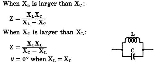
Inductance, capacitance, and resistance in parallel (Fig. 40)
Fig. 40

Inductance and series resistance in parallel with resistance (Fig. 41)
Fig. 41

Inductance and series resistance in parallel with capacitance (Fig. 42)
Fig. 42

Capacitance and series resistance in parallel with inductance and series resistance (Fig. 43)
Fig. 43
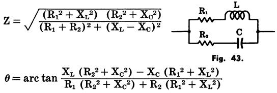
where,
Z is the impedance in ohms,
R is the resistance in ohms,
L is the inductance in henrys,
XL is the inductive reactance in ohms,
XC is the capacitive reactance in ohms,
θ is the phase angle in
degrees by which the current leads the voltage in a capacitive circuit or lags
the voltage m an inductive circuit. 0° indicates an in-phase condition.
OHM’S LAW FOR ALTERNATING CURRENT
The fundamental Ohm’s law formulas for alternating cur- rent are given by:
E = IZ, I = E/Z, Z = E/I
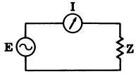
where,
E is the voltage in volts, I is the current in amperes, Z is the impedance in ohms.
The power expended in an ac circuit is calculated by the formula:
P = EI cosθ
where,
P is the power in watts, E is the voltage in volts, I is the current in amperes, θ is the phase angle in degrees.
The phase angle is the difference in degrees by which the current leads or lags the voltage in a reactive circuit. In a series circuit, the phase angle is determined by the formula:
θ = arc tan X/R
where,
X is the inductive or capacitive reactance in ohms, R is the nonreactive resistance in ohms.
Therefore:
For a purely resistive circuit:
θ=0°, cosθ= 1, P = EI
For a resonant circuit:
θ=0°, cos θ= 1,P = EI
For a purely reactive circuit:
θ = 90°, cos θ= 0, P=0
AVERAGE, RMS, PEAK, AND PEAK-TO-PEAK VOLTAGE AND CURRENT
Table 1 can be used to convert sinusoidal voltage (or cur- rent) values from one method of measurement to another.
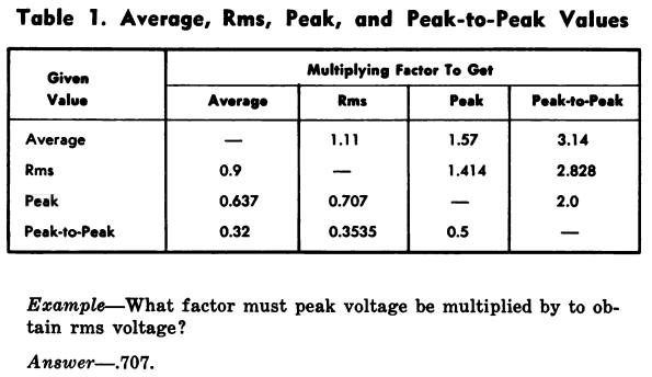
To use the table, first find the given type of reading in the left-hand column, then find the desired type of reading across the top of the table.
To convert the given value to the desired value, multiply the given value by the factor listed under the desired value.
VACUUM-TUBE FORMULAS
The following formulas can be used to calculate the vacuum-tube properties listed.
Amplification factor

Ac (dynamic) plate resistance

Mutual conductance (transconductance)

Gain of an amplifier stage

where,
µ is the amplification factor, Δ is the variation or change
in value, Eb is the plate voltage in volts,
Ec is the grid voltage in volts, Ib is the plate current in amperes, RL is the plate-load resistance in ohms,
rp is the ac plate resistance
in ohms, gm is the mutual conductance in mhos.
TRANSISTOR FORMULAS
The following formulas can be used to calculate the transistor properties listed.
Input resistance

Current gain

Voltage gain

Output resistance

Power gain

The current gain of the common-base configuration is alpha.

The current gain of the common emitter is beta.

A direct relationship exists between the alpha and beta of a transistor.


where,
α is the current gain of a common-base configuration,
Av is the voltage gain,
Ai
is the current gain,
Ar is the power gain,
β the current gain in a common-emitter configuration,
Ib is the base current,
Ic
is the collector current,
Ie is the emitter current,
Ii is the input
current,
Io is the output current,
Pi is the input power,
Po
is the output power,
Ri is the input resistance,
Ro is the output resistance,
Vb is the base voltage,
Vc
is the collector voltage;
Vi is the input voltage,
Vo is the output
voltage.
TRANSFORMER FORMULAS
In a transformer, the relationships between the number of turns in the primary and secondary, the voltage across each winding, and the current through the windings are ex- pressed by the equations:

By rearranging these equations, any unknown can be determined from the following formulas:
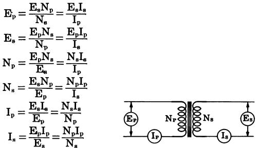
The turns ratio of a
transformer is determined by the following formulas.
A step-up
transformer

A step-down transformer

The impedance ratio of a transformer is determined by:

The impedance of an unknown winding is determined by the following formulas:
A step-up transformer

A step-down transformer

where,
Ep, is the voltage
across the primary winding, Es is the voltage across the secondary winding,
Np is the number of turns in the primary winding, Ns is the number of turns in the secondary winding,
Ip is the current through the primary winding, Is is the current through the secondary winding,
T is the turns ratio,
Z is the impedance ratio,
Zp is the impedance of the primary winding, Zs is the impedance of the secondary winding.
FREQUENCY AND WAVELENGTH FORMULAS
Since frequency is defined as the number of complete hertz (cycles per second) and since all radio waves travel at a constant speed, it follows that a complete cycle occupies a given distance in space.
The distance between two corresponding parts of two waves (the two positive or negative crests or the points where the two waves cross the zero axis in a given direction) constitutes the wavelength.
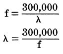
If either the frequency or the wavelength is known, the other can be computed as follows:
Where,
f is the frequency in kilohertz, λ is the wavelength in meters.
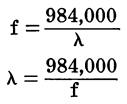
If it is desired to calculate the wavelength in feet, the following formulas should be used:
where,
f is the frequency
in kilohertz,
λ is the wavelength in feet.
The preceding formula can be used to determine the length of a single-wire antenna.
For a half-wave antenna:

For a quarter-wave antenna:

where,
L is the antenna length in feet, f is the frequency in megahertz.
FREQUENCY-TO-WAVELENGTH CONVERSION
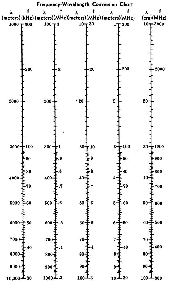
The wavelength of any frequency from 30 kHz to 3000 MHz can be read directly from the chart in Fig. 46. Also, if the wavelength is known, the corresponding frequency can be obtained from the chart for wavelengths from 10 centimeters to 1000 meters.
To use the chart, merely find the known value (either frequency or wavelength) on one of the scales, and then read the corresponding value from the opposite side of the scale.
Example
What is the wavelength of a 4-MHz signal?
Answer
715 meters. (Find 4 MHz on the third scale from the left. Opposite 4 MHz on the frequency scale we find 75 meters on the wavelength scale.)
TRANSMISSION-LINE FORMULAS
The characteristic impedance of a transmission line is defined as the input impedance of a line of the same con- figuration and dimensions but of infinite length.
When a line of finite length is terminated with an impedance equal to its own characteristic impedance, the line is said to be matched.
Coaxial Line The characteristic impedance of a coaxial line (Fig. 47) is given by:
Fig. 47

where,
Z, is the characteristic impedance,
D is the inside diameter of the outer conductor,
d is the outside diameter of the inner conductor expressed in the same units as D,
k is the dielectric constant of the insulating material (k equals 1 for dry air).
Fig. 46
The attenuation of coaxial line in decibels per foot can be determined by the formula:

where,
a is the attenuation in decibels per foot of line, f is the frequency in megahertz,
D is the inside diameter of the outer conductor in inches,
d is the outside diameter of the inner conductor in inches
Parallel-Conductor Line
The characteristic impedance of parallel-conductor line (twin-lead) is determined by the formula:

where,
Z, is the characteristic impedance,
D is the center-to-center distance between conductors,
d is the diameter of the conductors in the same units as D,
k is the dielectric constant of the insulating material between conductors (k equals 1 for dry air).
COIL-WINDING FORMULAS
The following formulas can be used to calculate the inductance of coil windings.
Single-Layer Coils The inductance of single-layer coils (Fig. 49) can be calculated to an accuracy of approximately 1% with the formula:
Fig. 49
Fig. 49

To find the number of turns required for a single-layer coil with a given inductance, the foregoing formula is re- arranged as follows:

where, L is the inductance in microhenrys, N is the number of turns, A is the mean radius in inches, B is the length of the coil in inches.
Multilayer Coils
The inductance of a multilayer coil (Fig. 50) of rectangular cross section can be computed from the formula:
Fig. 50

where, L is the inductance in microhenrys, N is the number of turns, A is the mean radius in inches, B is the length of the coil in inches, C is the depth of the coil in inches.
SINGLE-LAYER COIL CHART
The chart in Fig. 51 provides an easy method for deter- mining either the inductance or the number of turns for single-layer coils.
Fig. 51
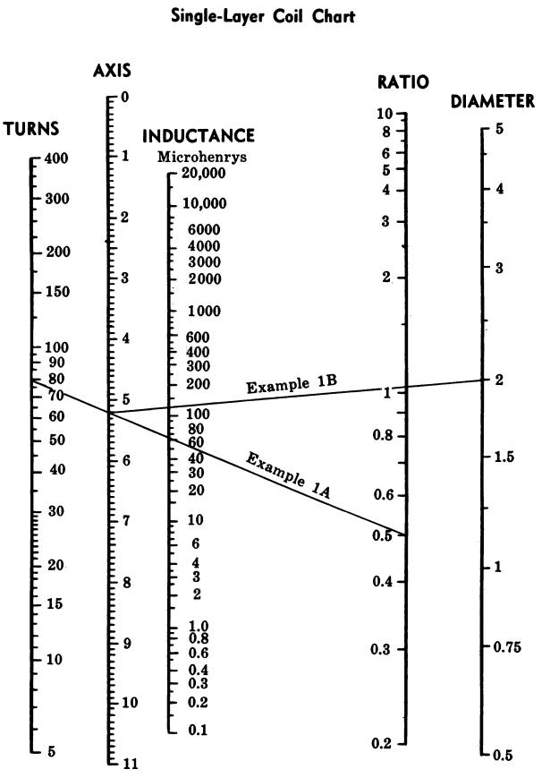
When the length of the winding, the diameter, and the number of turns of the coil are known, the inductance can be found by placing a straightedge from the “Turns” scale to the “Ratio” (diameter ~ length) scale and noting the point where the straightedge intersects the “Axis” scale.
Then lay the straightedge from the point of intersection of the “Axis” scale to the ‘“‘Diameter’’ scale.
The point at which this line intersects the “Inductance” scale indicates the inductance (in microhenrys) of the coil. The number of turns can be determined by reversing the procedure.
After finding the number of turns, consult a wire table to determine the size of wire to be used.
Example
What is the inductance of a single-layer coil having 80 turns wound to 4 inches in length on a coil form 2 inches in diameter?
Answer
130 microhenrys. (First lay the straightedge as indicated by the line labeled “Example 1A.” Then lay the straightedge as indicated by the line labeled “Example 1B.’’)
TIME-CONSTANT FORMULAS
A certain amount of time is required, after a de voltage has been applied to an rc or rl circuit, before the capacitor can charge or the current can build up to a portion of the full value. This time is called the time constant of the circuit.
However, the time constant is not the time required for the voltage or current to reach the full value; instead, it is the time required to reach 63.2% of full value.
During the next time constant, the capacitor is charged or the current builds up to 63.2% of the remaining difference, or to 86.5% of the full value.
Table 2 gives the percent of full charge on a capacitor, or current buildup in an inductance after each time constant.
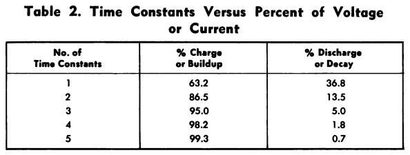
Theoretically, the charge on the capacitor, or the current through the coil, can never reach 100%. However, it is usually considered to be 100% after five time constants.
Likewise, when the voltage source is removed, the capacitor will discharge or the current will decay 63.2%, or to 36.8% of full value during the first time constant.
Table 2 also gives the percent of full voltage after each time con- stant for discharge of a capacitor or decay of the current through a coil.
The time per time constant is calculated as follows.
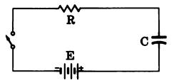
For an RC circuit (Fig. 52) : T=RC
Fig. 52
For an RL circuit (Fig. 53): T = L/R
Fig. 53
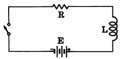
where, T is the time in seconds, R is the resistance in ohms, C is the capacitance in farads, L is the inductance in henrys
In addition, the values can also be expressed by the following relationships:

DECIBEL FORMULAS
The number of decibels (dB) corresponding to a given power ratio is 10 times the common logarithm of the ratio.
Thus:

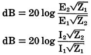
The number of decibels corresponding to a given voltage or current ratio is 20 times the common logarithm of the ratio. Thus, when the impedances across which the signals are being measured are equal, the equations are:

If the impedances across which the signals are measured are not equal, the equations become:
DECIBEL REFERENCE LEVELS
The decibel is not an absolute value; it is a means of stating the ratio of a level to a certain reference level.
Usually, when no reference level is given, it is 6 millivolts across a 500-ohm impedance. However, the reference level should be stated whenever a value in dB is given.
Other units, which do have specific reference levels, have been established. Some of the more common are:
dBk—1 kilowatt
daBm—1 milliwatt, 600 ohms
dBv—1 volt
dBw—1 watt
dBvg—voltage gain
dBrap—decibels above a reference acoustical power of 10-16 watt
VU—1 milliwatt, 600 ohms (complex waveforms varying in both amplitude and frequency).
DECIBEL TABLE
The decibel table shown in Table 3 lists most of the current, voltage, and power ratios encountered, with their decibel values.
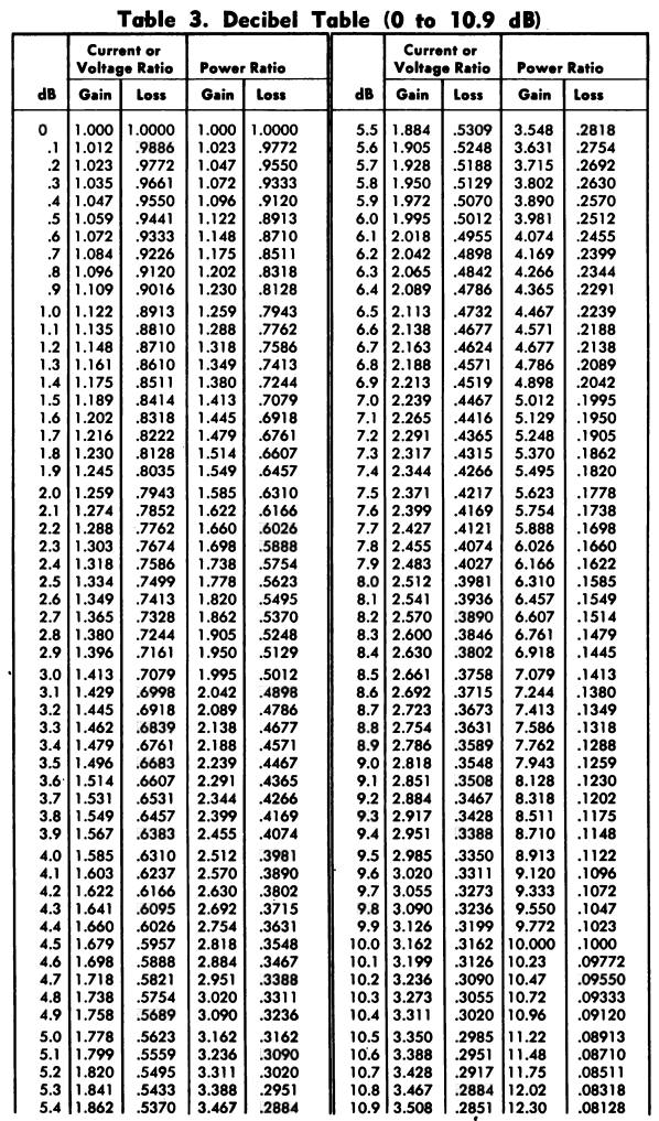
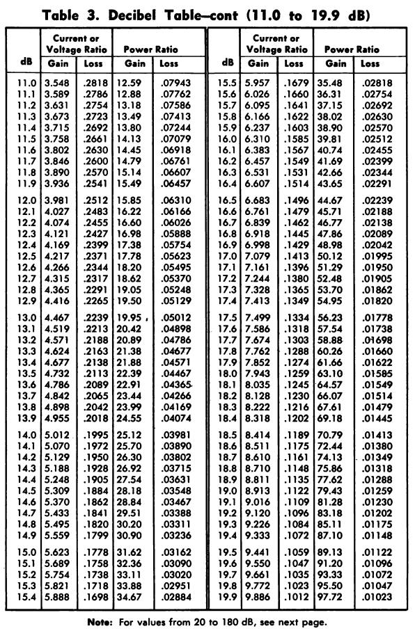
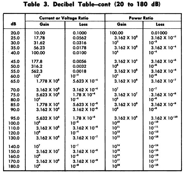
If a dB value is not listed and it is desired to find the corresponding ratio, first subtract one of the given values from the unlisted value (select a value so the remain- der will also be listed).
Then multiply the ratios given in the chart for each value.
To convert a ratio which is not given in the table to a dB value, first factor the ratio so that each factor will be a listed value; then find the dB equivalents for each factor and add them.
Example 1
Find the dB equivalent of a power ratio of .631.
Answer
2-dB loss.
Example 2
Find the current ratio corresponding to a gain of 43 dB.
Answer—141.
First find the current ratio for 40 dB (100); then find the current ratio for 3 dB (1.41).
Multiplying, 100 x 1.41 = 141.
Example 8—Find the dB value corresponding to a voltage ratio of 150.
Answer
43.5.
First factor 150 into 1.5 x 100.
The dB value for a voltage ratio of 100 is 40; the dB value for a voltage ratio of 1.5 is 3.5 (approximately).
Therefore, the dB value for a voltage ratio is 40 + 3.5 or 43.5 dB.
