Capacitors Charge and Discharge
The purpose of this project is two-fold: to demonstrate the Capacitor charge storage and to consider the operation of DC voltmeters.
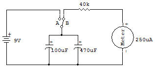
Both of these things are basic and therefore very important for your understanding of electronic circuits. Circuit action is demonstrated by first placing the slide Switch in position A (down) to allow the Capacitors to receive a 9V charge.
Then set the Switch to position B (up) to allow the DC voltmeter to be placed across the Capacitors in place of the Battery. You'll see the reading on the voltmeter decrease very slowly as the charge leaks off the Capacitors through the Meter.
When connected across the Battery., the Capacitors receive a charge of voltage because electrons from the negative Battery terminal enter the Capacitor and pile up on the (-) Capacitor electrode.
The same number of electrons are drawn off the (+) Capacitor electrode to make it deficient in electrons. When the charged Capacitor is placed across a conductive path, the Meter circuit in this case, the electrons from the (-) capacitor electrode flow through the circuit over to the (+) electrode until equilibrium is re-established.
The charge on the Capacitor at any instant of time is indicated by the reading shown on the Meter. The Meter is able to measure voltages by means of a proper current flow through the Meter.
The choice of total Meter circuit resistance controls the amount of voltage required to deflect the Meter to full scale. This resistance may be determined by application of Ohm's law, which states, "the resistance required to obtain a desired current is directly proportional to the applied voltage and inversely proportional to the current".
In formula form this is R=E/I R = Resistance (ohms), E=Voltage, I = Current (amps). In this formula, if we use volts and mA (milliamps or thousandths of an amp), the answer will be in K ohms (ohms x 1000).
The Meter in this circuit requires a current of about 0.25mA for a full scale reading. If you want a 10 volt Meter, the required resistance will be 10V divided by 0.25mA = 40K.
There doesn't happen to be a Resistor of this value, so we will use the next closest value of 47K.
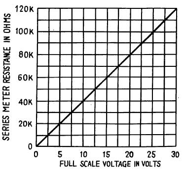
Now by using the graph included here we determine the actual full-scale voltage to be just a little under 12V. You can use the graph to construct other voltmeter ranges by using the series resistances indicated.
You can use separate series Resistors to obtain resistance values other than those you have. Remember, series Resistor values are added together to determine the total resistance.

![]()