C-MOS inverter
74HC00
C-MOS devices have a wider voltage range and draw much less power than other logic ICs.
C-MOS devices contain P-Channel MOS FETs (metal oxide semiconductor field effect transistors) and N-Channel MOS FETS, which are connected together internally. By the way, the "C" in C-MOS stands for "complementary", because the P-and N-Channel MOS FETs complement each other. (One is on while the other is off, and vice versa.)
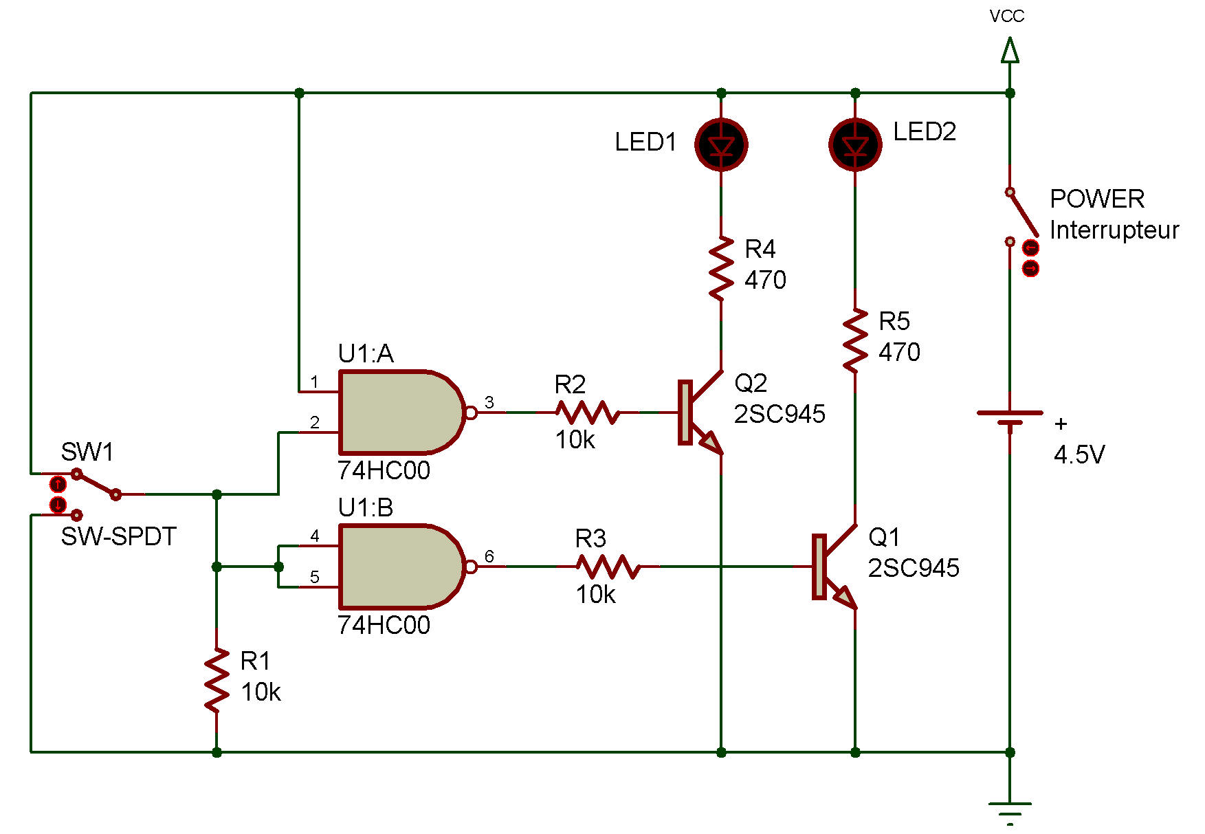
Digital C-MOS ICs contain various numbers of FETS, depending on the function of the IC. You can see from the schematic that this project uses two of the four NAND gates in the IC. Be aware, in circuits like this where some of the gates of the IC are not used, we have to connect the unused input pins to the positive or negative power supply. Otherwise, the IC can be damaged.
As you build this project, set the select switch Up. You'll notice that both LED 1 and LED 2 are off.
Since the output is 0, the input must be ... 1, of course! Now set the select switch down and both LEDs come on, indicating you're inputting 0. You can see why this happens by looking at the schematic.
With the select switch at the up position, both inputs to the two NANDs are 1. That means the output of both go to 0 (and turns off both transistors).
When the select switch is set to the down, we no longer have all inputs at 1... the outputs of NANDs are 1... transistors turn on... and the LEDs come on.

![]()