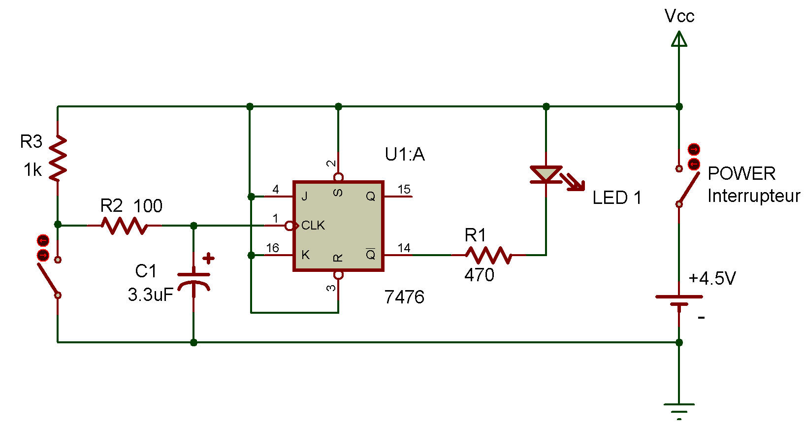
J-k toggle flip-flop
7476

The two flip-flop circuits contained in the Dual J-K Flip-Flop IC 7476 can be used in "toggled" applications.
This Project will show you how it's done. You can easily see how this circuit woiks by examining the schematic diagram. When you press the Key, you input a clock signal to the flip-flop, allowing it to quickly set and reset. And, as you can also see on the schematic, the output ai Q is used to control LED 1.
You're probably wondering how a J-K flip-flop circuit is different from an R-S flip-flop. The difference is in the J and K inputs — they're another way of controlling the flip-flop!
Here's how J and K control the flip-flop:
when both J and K are 0, Q stays at its last value (either 0 or 1) regardless of what the clock input is. When this happens, we say the flip-flop is latched. (For this operaiton, both R and S inputs must be at 1.)
But suppose that J is 0 and K is 1. When this happens, the flip-flop will reset when the clock changes from 1 to 0. When J is 1 and K is 0 the opposite will happen ... flip-flop.
When both J and K are at 1, every time the clock input changes from 1 to 0, it will reset and set alternately. One interesting use for J-K Hip-flops is in "master and slave" circuits (no, you don't use these circuits to build pyramids!).
A "master and slave" arrangement takes the output of one flip-flop (the master) and uses it for the J and K inputs of a second flip-flop (the slave).
Both the master and slave flip-flops use the same clock signal. Think a little bit about what could be done with a "master and slave" J-K flip-flop arrangement. Can you figure out a why to make such an arrangement "count?"
Be sure to make some notes about what you think!
