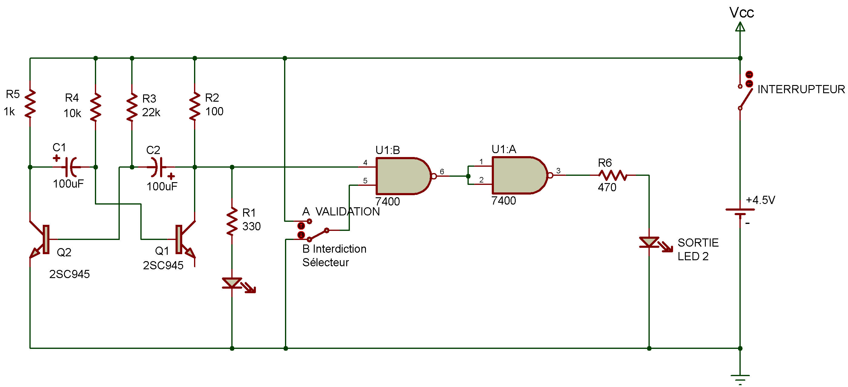
TTL AND enable circuit
7400
Our last Project had a characteristic that might be a problem in some situations. LEDs 1 and 2 take turns lighting on and going off.
We might want both LEDs to light on and off together. Did you figure out how to do this when you played with the last Project TTL NAND enable circuit?
If not, this circuit will show you how. If you look carefully at the schematic for this Project and the schematic for the last Project, you'll notice that they're almost identical. The only change is the addition of another NAND gate can you guess what effect this has on the operation of the circuit?
Just like our Last Project, setting the Select Switch to B will block the channel from LED 1 to LED 2.
But when you set the Select Switch to A, you'll see LED 2 light and go off together with LED 1. The two NAND gates together make up an AND gate (remember from Project AND gate?).
In a circuit like this, LED 1 is often referred to as the data input. LED 2 is often called the output. These terms are often used with enable circuits and pop up from time to time when we talk about digital electronic. (Remember our definitions back in Project An inverter circuit).
You might suspect by now that we can use other digital circuits to perform an enable function. Can you figure out how?
Be sure to keep notes of what you figure out especially if you figure out how to use an OR gate in an enable circuit. (There's a reason why, as you'll discover in the TTL OR enable circuit.)

![]()