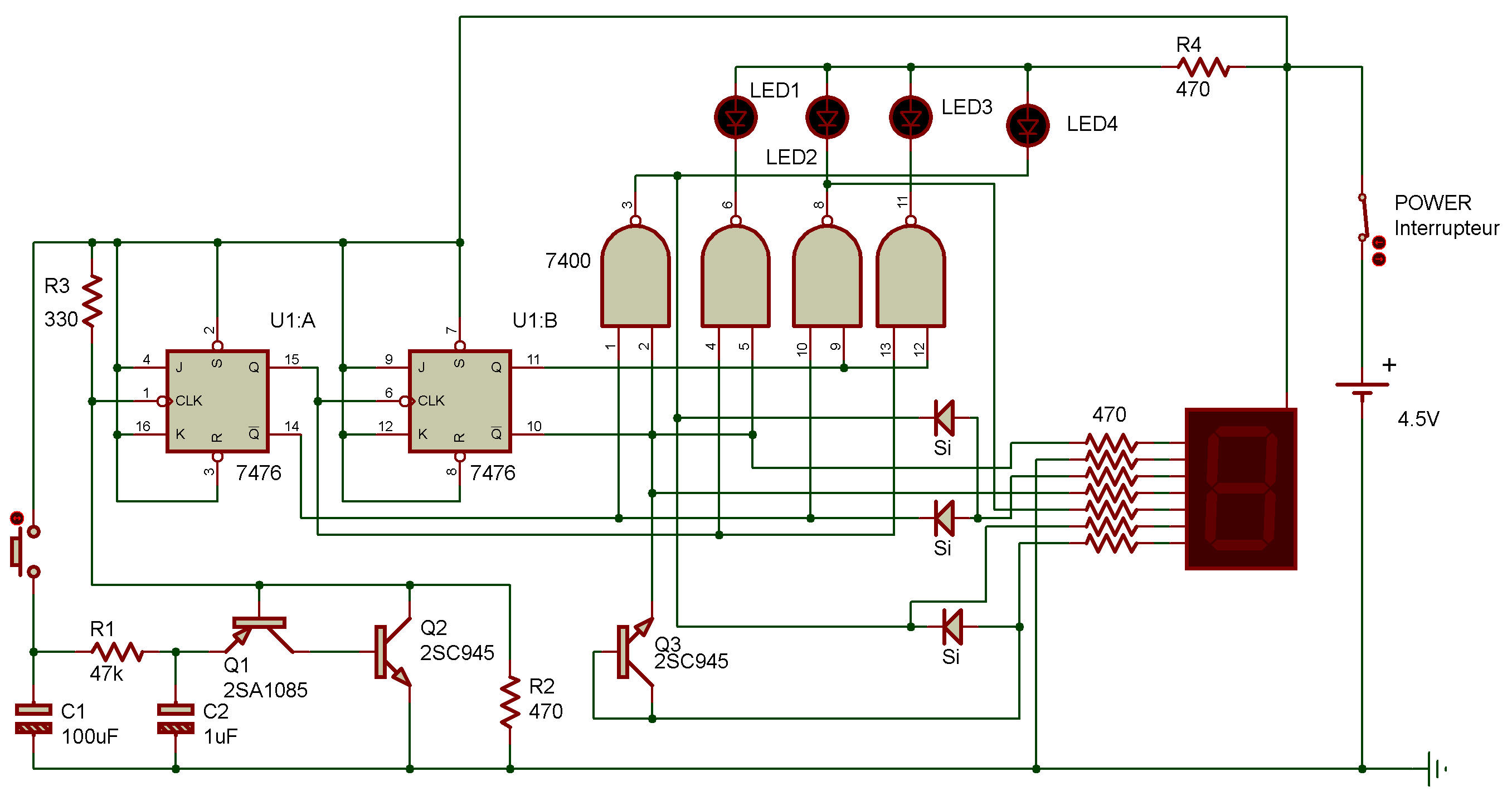
Electronic roulette
7400, 7476
Be careful in constructing this one — there are many wiring connections. Take your time and double-check your work.
When you're finished, turn the power to ON and press the Key. Hold it down for a few seconds. You'll see the four LEDs flash off and on rapidly. On the Display you'll see the numbers 1 through 4 indicated in order very rapidly.
Now release the Key. The LEDs and Display will "slow down" and finally stop at one LED and its corresponding number.
As you might suspect, the two Transistors generate the clock signal for the R-S flip-flops. Note from the schematic that the clock signal for the second R-S flip-flop comes from output Q of the first flip-flop.
The combined outputs of the R-S flip-flops then are applied to the NAND gates, which in turn light and turn off the LEDs. As you might also suspect, the discharge of the 100 µF capacitor controls how long the clock signal is generated.
Notice how many R-S flop-flops and NAND gates were used in this circuit. You see, there are actually two R-S flip-flops in the Dual J-K Flip-Flop IC and four NAND gates in the Quad 2-input NAND IC.
That's what the "integrated" means in integrated circuit — there are actually several circuits inside each IC!

![]()