
Schmitt Trigger Circuit
NE5532
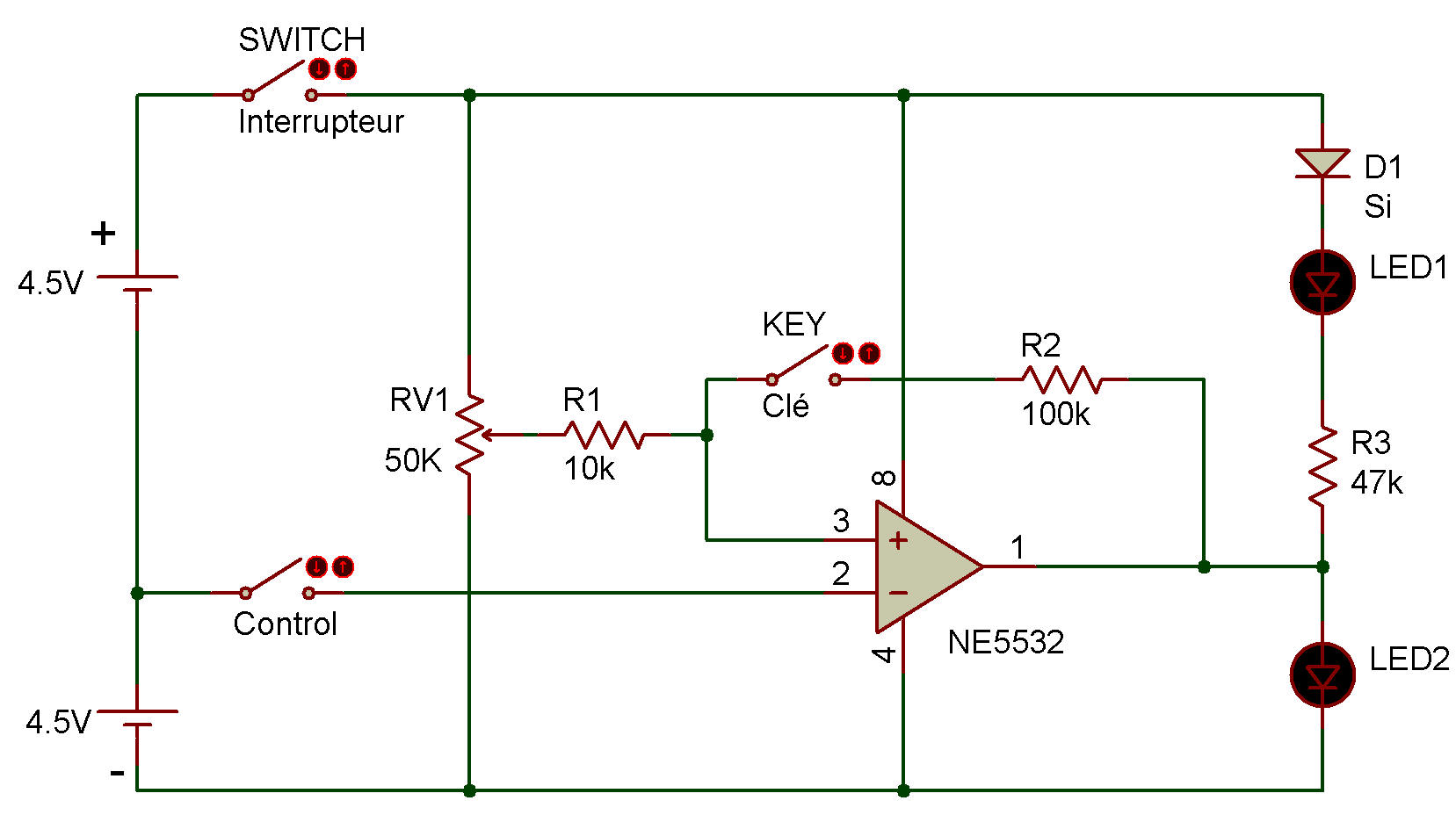
We're going to use the operational amplifier as a Schmitt trigger circuit and as a comparator. The operational amplifier produces a signal as long as its input voltage exceeds a certain value. Look at the schematic: can you see how it works?
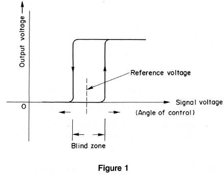
It shows that the voltage level that causes the output to turn on is higher than the voltage level that stops the output. It looks like the Schmitt trigger circuit resists to change the output state. We call such operation as "hysteresis loop." Now, lets get to the experiment.
First leave the key off. The operational amplifier works as a comparator in this state. When you rotate the control, LEDs 1 and 2 take turns lighting at some point. Note that this point doesn't change whether you turn the control clockwise or counter clockwise.
Now, press the key on, and you'll have a Schmitt trigger circuit that produces hysteresis loops, as shown in Figure 1.
The width of hysteresis becomes narrower as the R2/R1 increases. Notice how the width changes when by using different value for R1 and R2.
![]()