
A Push-Pull Oscillator
We've already seen a push-pull amplifier in operation (Project A Push-Pull Amplifier in Amplifier Section), so why not an oscillator?
This Project shows you how to build one. Once you finish the wiring connections, hold the Key down and listen to the sound from the Speaker. Can you think of any advantages this oscillator circuit has over the circuit in our last Project Understanding Oscillators?
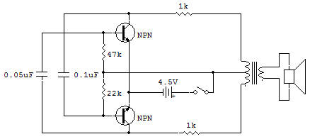
One big advantage is more efficient operation. Notice how feedback comes through the 0.05 uF and 0,1 uF capacitors connected to the Transformer's coil. But see how each capacitor is connected at the ends of the Transformer's coil. This means that when one capacitor is charging, the other is discharging. And this means ...
... that when one Transistor is off the other is operating. There's always one Transistor operating, unlike the previous Project where the Transistor was switching on or off during operation. Since the 0,05 uF and 0.1 uF capacitors control circuit operation, try using different values of capacitors in their place.
And since the 47K and 22K resistors control the emitter-to-base current, try using different values in their place and see what happens. Be sure to keep notes of what you discover.
What effects do higher and lower values have upon operation? You'll find this information handy when you start designing your own oscillator circuits.
![]()