Parallel Resistors
You might think from our last Project that you always increase the resistance in a circuit whenever you add another resistor. Not so — in fact, you can even decrease the resistance in a circuit by adding another resistor. Let's take a look at this Project and see if we can figure out how this happens.
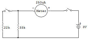
In the schematic, you'll notice that the two resistors are side by side, not one after the other. This side by side arrangement is known as parallel connection.
With the Select Switch at A (like the schematic), only the 33K Resistor is in the circuit. Setting the Select Switch to B adds the 22K Resistor.
Set the Select Switch to A and put ON the circuit. Note the reading on the Meter.
Now set the Select Switch to B-looks what happens to the Meter!
More electricity flowed in the circuit with the extra resistor. Seems impossible, but look at the schematic for this Project.
In a parallel arrangement, only a part of the total electric current flows to each resistor. In fact, the total resistance in a parallel circuit is always less than the lowest value resistor connected in parallel. In this Project the total resistance would be less than 22K. As you can see, parallel resistor connections prove that more is sometimes less!
the formula for Parallel Resistors is:
1 / RT = 1 / R1 + 1 / R2 + ... 1 / RN
for 2 Parallel Resistors only the formula is
RT = (R1 x R2) / (R1 + R2)
RT = (22 x 33) / (22 + 33) = 726 / 55 = 13,2 K

![]()