
DC-to-DC Converter
This project shows how a DC voltage can be changed into AC, put through a Transformer and then converted back to a DC voltage. The DC voltage is changed to AC by the oscillator circuit.
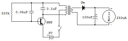
This oscillator circuit uses the 2SA Transistor to obtain the necessary gain greater than 1, and the Transformer to obtain the necessary phase reversal and feedback to sustain oscillations. The 220K Resistor provides a DC current to the base of the Transistor to bias it on. The 0.05uF and 0.1 uF Capacitors are used to obtain a desired amount of feedback and a more useful waveshape of AC voltage.
The AC across the primary winding of the Transformer is coupled to the secondary by the magnetic field within the Transformer. The secondary AC is rectified by the Ge half-wave rectifier Diode, filtered by the 100uF Capacitor, and then delivered to the meter as a relatively pure DC.
This type circuit finds application where a low voltage DC is available but a higher DC voltage is needed. It is also usable where a voltage must be transported over long distances though wires. .If the DC were sent out over the transmission wires the losses would be high and efficiency would be low.
At the end of the line the AC voltage is transformed down to the desired level of AC which may then be converted back to DC as required. This is a good project for experimenting with different values for Capacitors and Resistors in the oscillator circuit.
Be a good experimenter and record all your results. You can try any value of Capacitor in place of the 0.05uF and 0.1 uF, but don't go below 100K in value for the 220K Resistor or the Transistor and Meter may be damaged. You can hear what the oscillator sounds like if you connect the crystal Earphone across the Transformer (either winding).
![]()