
Delay Switching Circuits
The purpose of this project is to study delay switching circuits as used in computer and logic control. The circuits make use of the fundamental property of all Capacitors, the storage of charge.
Many control circuits are required to either turn a circuit OFF after a required delay time or to turn the circuit ON after a required delay time. The most basic and simple control uses the ability of a Capacitor to store a charge of electricity. The charge can be made to pass though a series resistance to slow down the time required to initially charge a Capacitor. This is used to provide a delay in the turn ON of a circuit.
When the charge on a Capacitor voltage is allowed to slowly be removed by a parallel resistance, a delay in the removal of Capacitor voltage is obtained that is used to control the turn OFF of a circuit.
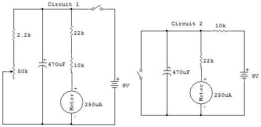
Hook up the first circuit (1) to check operation. Try both high and low control settings. Notice that the Meter indicates the voltage across the Capacitor. The series resistance to the Meter has been chosen to obtain a full scale Meter reading with the 9V Battery.
Let's assume that the circuit to be controlled requires at least a half-scale Meter reading to be ON, all voltages below this indicate an OFF condition. This circuit provides a fast on but a delayed OFF. Use a watch or clock which has a second hand and record the time delay this circuit can provide. Use the 5 Meter reading as the switching level from ON to OFF seconds maximum and seconds minimum. From about 14 to 2 seconds is typical.
Hook up the second circuit (2) and check operation. This provides the opposite action of circuit 1 (e.g., it provides a slow ON and a fast OFF). Measured delay is seconds. About two seconds is typical. Now let's consider what causes this delay in the charge or discharge of a Capacitor.
Notice that the fast ON circuit has no resistance between the Battery and Capacitor, and that the fast OFF circuit places a zero resistance (short circuit) across the Capacitor to obtain a fast discharge. When these conditions are compared with the slow OFF and slow ON circuit conditions we see resistances through which the Capacitor charging or discharging current must pass. It is the combination of resistance (R) and capacitance (C) then which is seen as the controlling factor.
The product of RC in the circuit is called the "time constant". The higher the product of RC, the longer the time delay to either charge or discharge the Capacitor.
![]()