
RF power detector with LED display
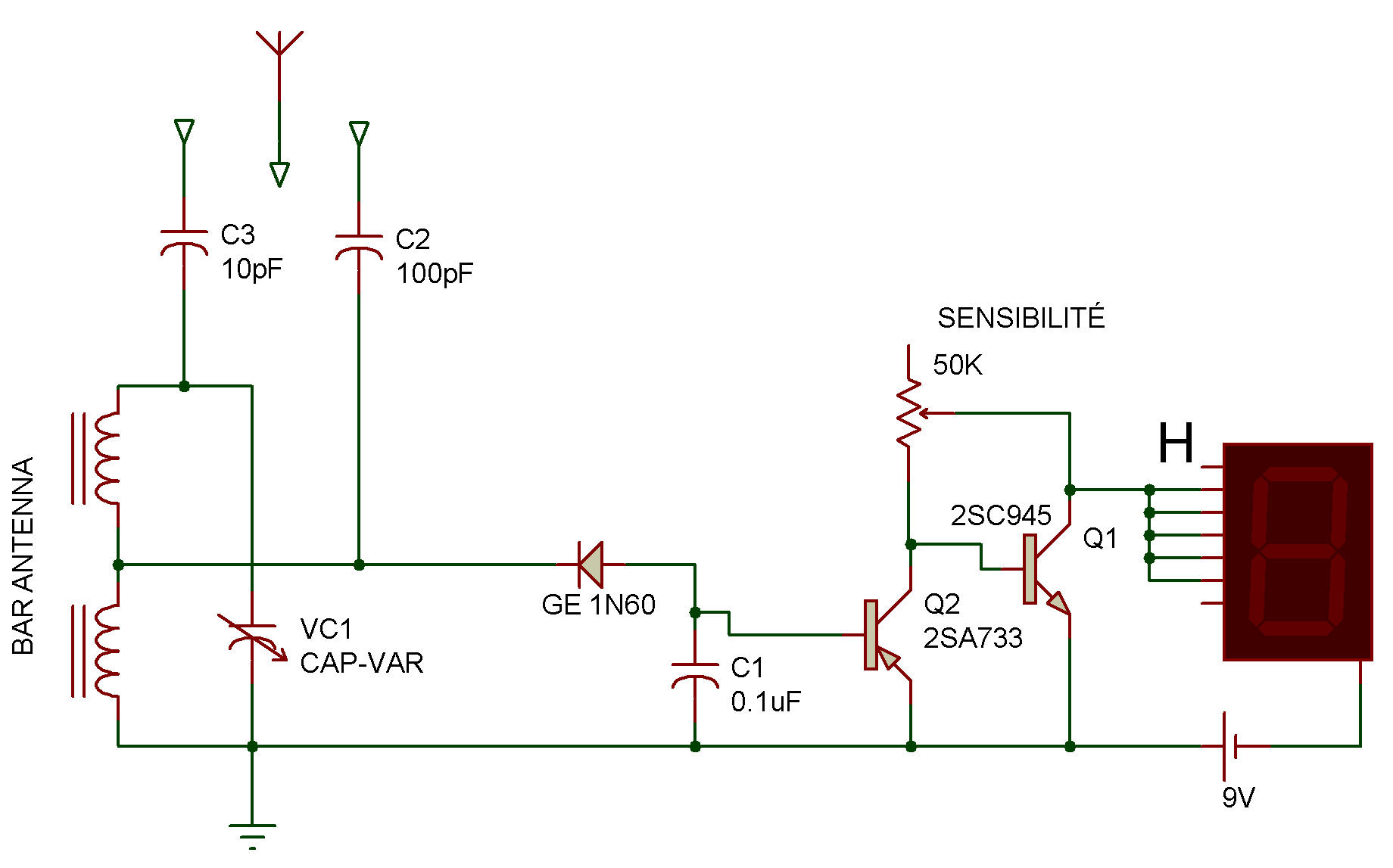
Here is a real good way to indicate this with a high level of RF on AM radio band by lighting the letter H on the board LEDs. A sensitivity control is for you to adjust the response characteristics over a wide range.
The parallel resonant RF circuit is typical to all other RF receivers circuits. The detector diode has an output filter higher than normal, a 0.1 uF, so as to filter the output for that same modulation is filtered in the CC.
The DC detector output puts the transistor 2SA on. This in turn allows the 2SA of the detector current to be in parallel to the input of 2SC as desired. This control method uses the normal leakage current 2SA such a way that the LED can be partially switched on without an RF signal is present from the parallel resonant antenna circuit.
This actually lowers the threshold voltage required to turn the LED on at a certain desirable brightness. You can do the monitoring stations by connecting the listener through terminals C-E of the 2SC.
![]()