
Shunt Type Ohmmeter
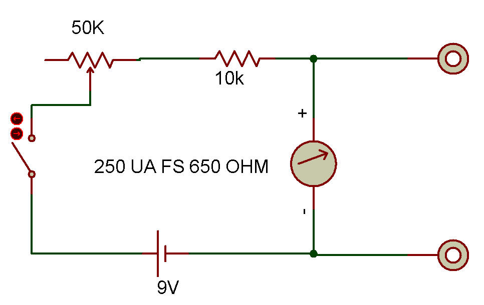
The purpose of this project is to study the basic shunt type ohmmeter. These ohmmeters are used mainly to measure low values of resistance. The circuit is a very simple and reliable series circuit with the Probes brought out from across the Meter.
The unit constructed in this project has a center scale resistance of about 650 ohms. The recommended range for measurements with reasonable accuracy is from about 30 to 10,000 ohms. Ohmmeter operation is as follows:
1. Turn ohmmeter ON with the slide Switch.
2. Adjust 50K Control for a scale reading of 10 on the top (blue) scale.
3. Place the Probes across the resistance to be measured. Make sure the circuit under measurement has NO voltage present or this Meter may be damaged. Also make sure no parallel resistances are present (including your hands).
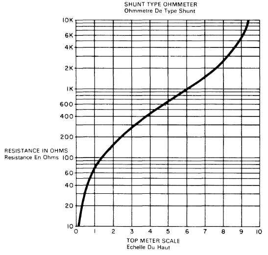
4. Determine the resistance from the graph below or from the formula:

where R is the resistance being measured, and I is the top (blue) Meter calibration with R in the circuit
This circuit works by supplying a constant current to the Meter from the series circuit com posed of the 10K, 50K and 9V. The current is adjusted to the Meter full scale value.
Now as shunting resistance R is placed across the Meter, the current divides between the Meter resistance and the resistance of R, depending on the ratio of resistances. Since the total current is constant and equal to the 10 calibration mark on the Meter, the amount of Meter deflection may be calibrated directly in ohms for the resistance shunting (paralleling) the Meter.
You can use this Meter to measure about anything in the kit (except components being used in this circuit) without problem. The main thing to always remember is to NEVER place the ohmmeter Probes across voltage (including charged Capacitors). Measure such things as the Relay winding, Transformer windings and low-value resistors.
![]()