NPN transistor switch
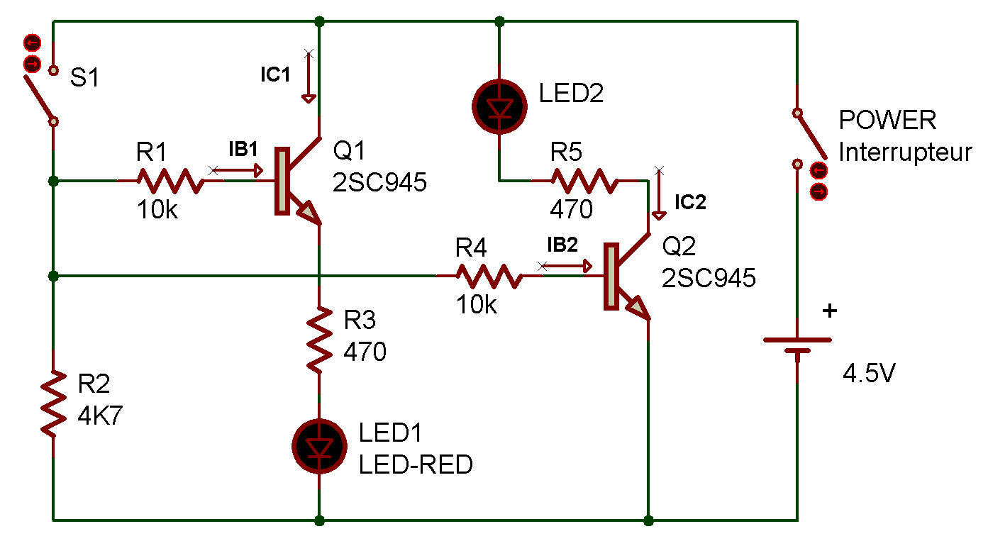
The experiment in this project shows you how an electronic switch using two NPN transistors works. Note that this circuit is very much alike to previous one PNP transistor switch, but the direction of current flow is opposite. As you can see in the schematic, the LEDs are connected to the emitter of Q1 and to the collector of Q2.
We'll see how these transistors work as switches. When you finish wiring up the connections, switch power ON and see if any of the LEDs lights up. None of them light up, do they?
Turn S1 ON and you see that both LEDs light up. This means that Ib1 and Ib2 flowing from S1 are very small, but they can switch the flow of the large currents Ie1 and Ie2 to turn the LEDs ON.

![]()