Transistor Circuit Action
We leave the simple Diode and look at the Transistor. The Diode can only conduct or not conduct, it has only two leads.
A Transistor has 3 leads and the third lead can be used to control what is happening between the remaining 2 leads. We say a Transistor can "amplify", that is, a small signal can control or produce a large signal.
This project demonstrates two methods of transistor control. One method involves removing the base-bias by shunting (bypassing), the other involves applying base-bias.
The LED readout is used to indicate these two different methods by lighting either the top or bottom half of the number zero (or letter "0" if you like). Circuit operation is as follows:
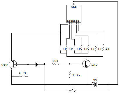
With the Key open, the 2SC is full ON because of base-bias current that flows through the 1K current limiting Resistor. This turns the LED top segments (A, F and B) ON. At this time, the 2SA is OFF because no base-bias current can flow. A negative base current source is required for a 2SA because current must always flow against the arrow head symbol in a Transistor (just like in a Diode). Any current that might attempt to flow from the base circuit of the 2SC cannot, because the germanium (Ge) Diode would be reverse-biased.
When the Key is closed, the 2SC is turned OFF because the Diode conducts. The voltage drop across the Diode is lower than that required to allow the 2SC to conduct, especially with the LED segments in the emitter circuit. The 2SA is turned ON at this time because of the base-bias current, which can flow though the 4.7K to the base. This lights LED segments E, D and C.
The 2.2K Resistor is needed to completely cut OFF the 2SA when the Key is up. Without this . Resistor the Transistor leakage (ICEO) might be sufficient to dimly light the LED segments driven by this Transistor.

![]()