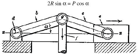
Fig. 1
Toggle Joint
A link mechanism commonly known as a toggle joint is applied to machines of different types, such as drawing and embossing presses, stone crushers, etc., for securing great pressure. The principle of the toggle joint is shown by Fig. 1. There are two links, b and c, which are connected at the center. Link b is free to swivel about a fixed pin or bearing at d, and link e is connected to a sliding member e. Rod f joins links b and c at the central connection. When force is applied to rod f in a direction at right angles to center-line xx, along which the driven member e moves, this force is greatly multiplied at e, because a movement at the joint g produces a relatively slight movement at e. As the angle α becomes less, motion at e decreases and the force increases until the links are in line. If R = the resistance at e, P = the applied power or force, and α= the angle between each link, and a line x–x passing through the axes of the pins, then:
Fig. 1
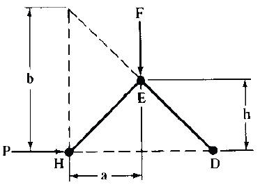
If arms ED and EH are of unequal length then
P = (F × a) ÷ b
The relation between P and F changes constantly as F moves downward.
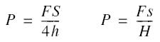
If arms ED and EH are equal, then
P = (F × a) ÷ 2h
A double toggle-joint does not increase the pressure exerted so long as the relative distances moved by F and P remain the same.
Toggle-joints with Equal Arms
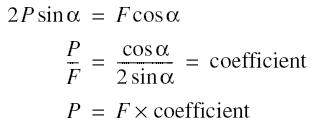
where F = force applied; P = resistance; ανδ, α = given angle.
Equivalent expressions (see diagram):
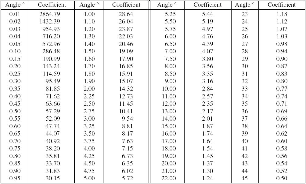
To use the table, measure angle α, and find the coefficient in the table corresponding to the angle found. The coefficient is the ratio of the resistance to the force applied, and multiplying the force applied by the coefficient gives the resistance, neglecting friction.

![]()