IR Led Proximity Sensor Circuits
Circuits de capteurs de proximité à LED infrarouges
|
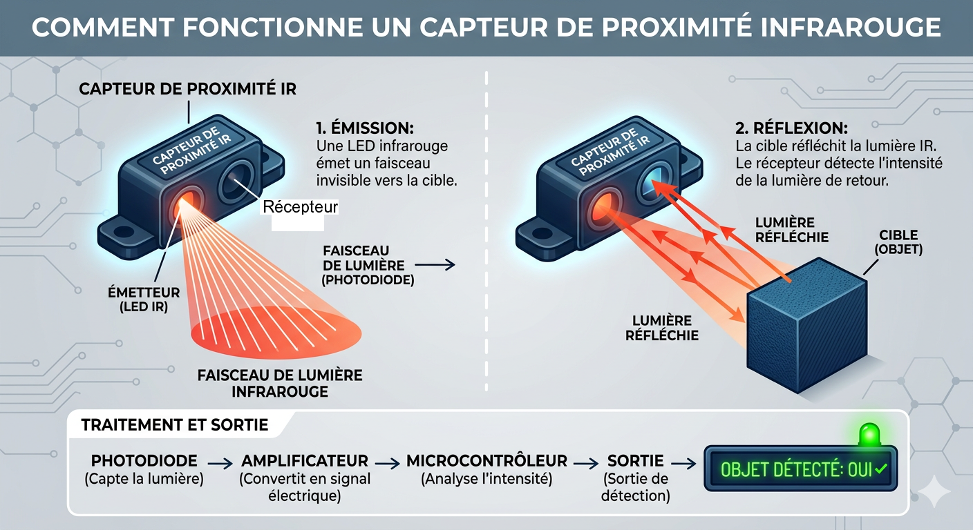
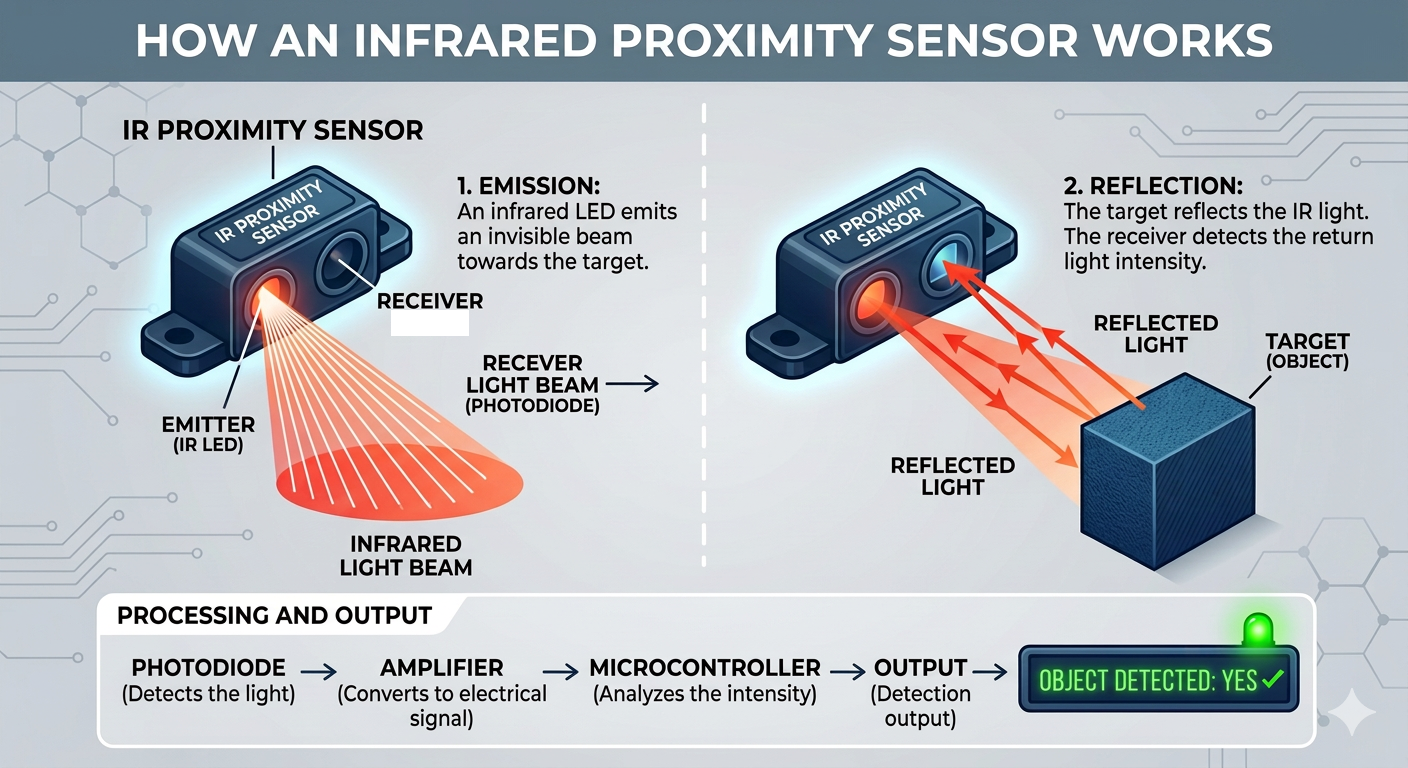
Un capteur de proximité infrarouge est un dispositif qui détecte la
présence d'un objet ou d'une personne lorsqu'elle se trouve à une
distance prédéterminée du capteur, grâce à des faisceaux infrarouges
réfléchis. Deux concepts de capteurs de proximité utiles sont expliqués ici. |
An IR proximity sensor is a device which detects the presence of an
object or a human when it is within a predetermined range from the
sensor, through reflected infrared beams. Two useful proximity sensor concepts are explained here. |
|
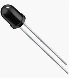
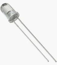
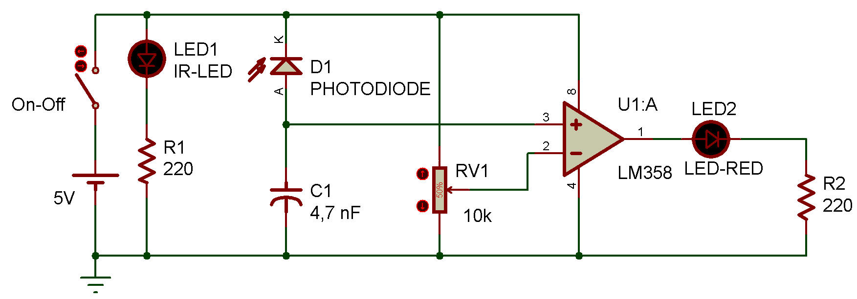
Fonctionnement Le principe de fonctionnement d'un capteur de proximité est relativement simple. Un capteur typique utilise deux LED en parallèle : une LED émettrice d'infrarouges et une photodiode. Ils fonctionnent comme un émetteur-récepteur. Lorsqu'un obstacle se trouve devant les rayons émis par la LED émettrice, ceux-ci sont réfléchis et interceptés par la photodiode réceptrice. Grâce aux propriétés de la photodiode, les rayons infrarouges interceptés diminuent sa résistance, générant ainsi un signal électrique. Ce signal correspond à la tension aux bornes d'une résistance de 10 kΩ, qui est directement appliquée à l'entrée non inverseuse d'un amplificateur opérationnel. |
How it work The principle lying behind the working of a proximity sensor is fairly simple. A typical concept has two leds parallel to each other – IR emitting led and a photodiode. They act as a transmitter-receiver pair. When an obstacle comes in front of emitter rays, they are reflected back and intercepted by the receiver. As per the properties of the photodiode ,the intercepted IR rays decrease the resistance of the photodiode and the resultant electric signal is generated. This signal in practice is the voltage across the 10k resistor which is directly fed to non-inverting end of op-amp. |
 |
|
 |
|
|
Le rôle de l'amplificateur opérationnel est de comparer les deux signaux
d'entrée qui lui sont appliqués. Le signal provenant de la photodiode est appliqué à l'entrée non inverseuse (broche 3) et la tension de seuil du potentiomètre est appliquée à l'entrée inverseuse (broche 2). Si la tension sur l'entrée non inverseuse est supérieure à celle sur l'entrée inverseuse, la sortie de l'amplificateur opérationnel est à l'état haut ; sinon, elle est à l'état bas. En résumé, dans ce circuit, l'amplificateur opérationnel convertit un signal analogique en un signal numérique. |
The function of the op-amp is to compare the two inputs given to it. The signal from the photodiode is given to the non-inverting pin (pin 3) and the threshold voltage from potentiometer is given to the inverting pin (pin 2). If the voltage at the non-inverting pin is greater than the voltage at the inverting pin the op-amp output is high otherwise the output is low. All in all, op-amp converts analog signal into digital signal in this circuit. |
|
SORTIES : Le signal de sortie du capteur peut être utilisé sous deux formes : ANALOGIQUE et NUMÉRIQUE. La sortie numérique est soit à l'état haut, soit à l'état bas. Le signal de sortie numérique d'un capteur de proximité peut être utilisé pour arrêter le mouvement d'un robot évitant les obstacles. Dès qu'un obstacle s'approche suffisamment, le signal peut être directement transmis aux broches d'entrée du contrôleur de moteur pour arrêter les moteurs. La sortie analogique est une plage de valeurs continues, de zéro à une valeur finie. Ce type de signal ne peut pas être directement appliqué aux contrôleurs de moteur ni à d'autres dispositifs de commutation. Il doit d'abord être traité par le microcontrôleur et converti au format numérique via un convertisseur analogique-numérique (CAN) et un codage. Ce type de sortie nécessite un microcontrôleur supplémentaire, mais évite l'utilisation d'un amplificateur opérationnel. |
OUTPUTS: The sensor output can be used in two forms: ANALOG and DIGITAL. Digital output is in the form of either high or low. Digital output signal of a proximity sensor can be used to stop the motion of an obstacle-avoiding robot. As soon as, the obstacle comes close enough, signal can be directly fed to the input pins of motor driver to stop the motors. Analog output is a continuous range of values from zero to some finite value. Such signal cannot be directly given to motor drivers and other switching devices. First they need to be processed by the microcontrollers and converted into digital form through ADC and some coding. This output form requires an additional microcontroller but eliminates the use of op-amp. |
 |
|
| Capteur de proximité avec relais et circuit intégré LM358 |
Proximity Sensor with a Relay and IC LM358 |
 |
|
![]()