Logic "OR" with LED Display
The purpose of this project is to study a logic OR circuit as used in computers. The readout is connected to display the letter H when either terminal A OR B is connected to terminal H.
These letters all mean something in logic work, A and B are the logic input terminals, H is a logic high (ON), and L is a logic low (OFF).
The H terminal is on the most negative part of the circuit therefore this is called "negative logic". A Truth Table for the logic OR function is as follows:
|
A |
B |
Output |
|
L |
L |
L |
|
L |
H |
H |
|
H |
L |
H |
|
H |
H |
H |
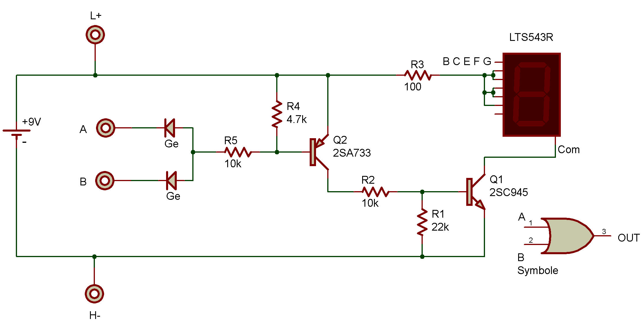
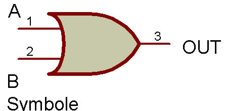
Expressed in words, either A OR B must be high for the output to be high. The logic symbol is also shown along with the Schematic.
This logic function, is generally written as A + B, where the + sign is used in place of the word OR and is read as "OR". Circuit operation is as follows:
Whenever both A and B are on L there is no source of base current for the 2SA, so it is in the OFF state. The 4.7K Resistor insures that it is completely OFF by allowing C-B leakage current to flow outside the B-E junction.
When OFF, the 2SA acts like a virtual open circuit between the collector (C) and emitter (E). This removes the source of base current from 2SC to keep it OFF as well. The 22K removes the possibility of any remaining 2SA leakage current from turning 2SC ON by shunting the current around the B-E junction. The LED has no current and is therefore dark.
When either A or B is connected to H it completes the base-bias circuit through the 10K to the 2SA, turning ON this Transistor. The 2SA Transistor completes the base-bias circuit through the second 10K to the 2SC, turning this Transistor ON. Current can now flow to the LED through the virtual short circuit between the C-E circuit of the 2SC Transistor.
Connecting both A and B to H gives the same results as for either terminal alone as the only difference is that the Diodes are in parallel. Parallel Diodes act the same as a single Diode. For this particular circuit an open (not connected) input terminal functions the same as a logic low.
This condition is not true for all logic circuits, see the AND circuit of project Logic "AND" with LED Display. You can use your VOM to measure circuit voltages during the two conditions of circuit operation. Transistor C-E voltage should be high when the Transistor is OFF and low when it is ON.

![]()