Logic "NOR" with LED Display
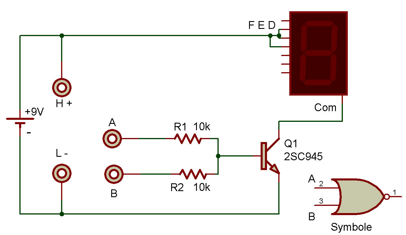
The purpose of this project is to study a logic NOR circuit as used in computers. The readout is connected to display the letter L when either terminal A or B is connected to terminal H+.
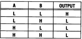
These letters all mean something in logic work, A and B are the logic inputs, H is a logic high, and L is a logic low. The output goes to low (L) only when both A and B are on terminal L-. This output condition is the opposite of the OR circuit, so this is referred to as the "inverted OR" or simply a NOR circuit.
The Truth Table for the logic NOR function is as follows:
Expressed in words the NOR function is:
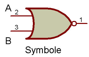
Whenever either A or B are high the output is low. The logic symbol is shown along with the Schematic.
This function is also written as
 , where " + " is
the OR sign and the bar over the symbol indicates inversion.
, where " + " is
the OR sign and the bar over the symbol indicates inversion.
Circuit operation is as follows:
When either 10K Resistor is connected to the positive H terminal, sufficient base-bias is supplied to the 2SC to turn it ON.
Anytime the 2SC is ON the LED receives current through the virtual short circuit between the 2SC's collector and emitter terminals.
The LED is wired to display the letter L for low. Having both 10K Resistors connected to H doubles the base-bias current and simply turns the Transistor ON harder.
When both A and B terminals are on the negative low terminal L, the Transistor can receive no base-bias and is in the OFF state. This state causes the Transistor to act as an open circuit between the collector (C) and emitter (E). This virtual open circuit blocks current from flowing to the LED.
The LED is therefore dark (indicating an output high state). You can use your VOM to verify circuit operation. When OFF, the Transistor C-E voltage approaches the supply voltage (7V at this time due to LED threshold voltage), and when ON this C-E voltage is only a few tenths of a volt (at the most).
For this particular circuit an open input terminal functions just like a low input. Remember, normal operation of a logic circuit is with the input always connected to either a high or a low.
NOTE:
Catch that output indication switch again? A high output is blank and a low output is "I" on the LED. Can you think of some ways in which such reverse logic output is useful?

![]()