Be your own multivibrator
7400, 7476
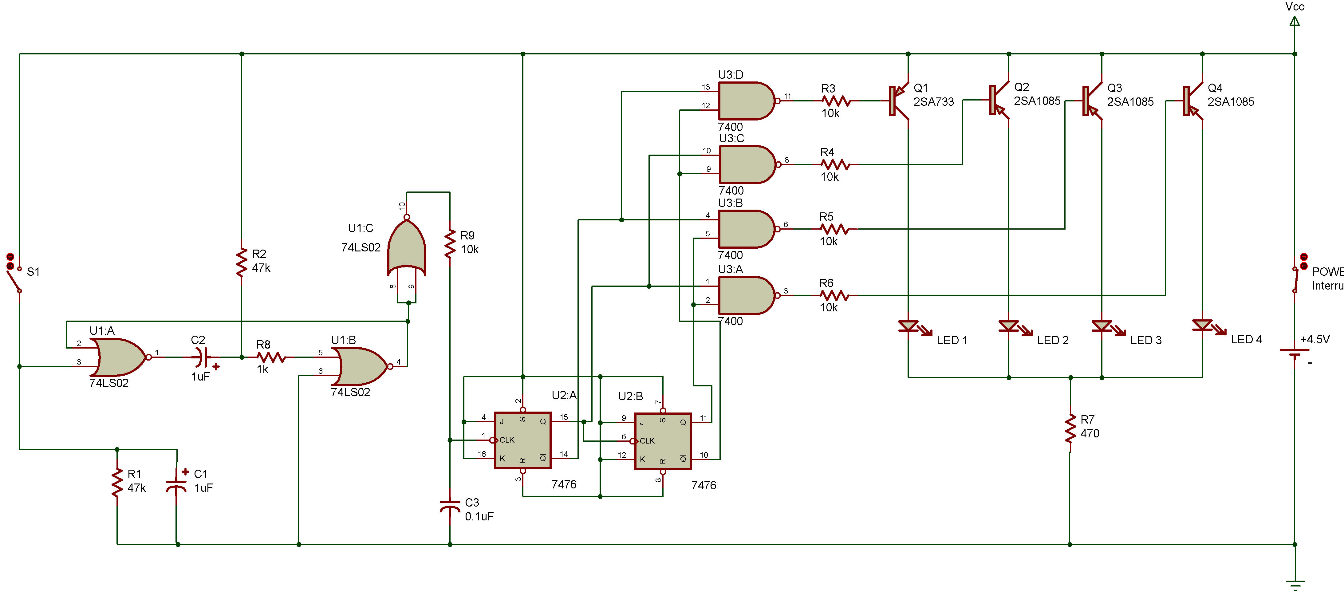
Notice anything familiar about the schematic for this project?
If you get the feeling that you've seen this circuit before, you're right. Take a look back at the schematic for project Divide by 4 counter with line decoder, you'll see that it's the same counter and line decoder circuit without the multivibrator. The project lets you be your own multivibrator.
As you can see from the schematic, each time you press S1 you send a clock signal to the first flip-flop. The counter circuit is asynchronous since the Q output of the first flip-flop provides the clock signal for the second flip-flop.
Turn power ON and press S1 a few times. You'll see LEDs 1 through 4 light up in order and then go off. This cycle is repeated a few times depending on how many times you press S1. Of course, there's several ways to vary this circuit.
You could supply the set or reset signal instead of the clock ... or you could let the multivibrator supply some of the inputs while you supply the others. Back in project Divide by 4 counter with display we told you that you could substitute a S1 for a multivibrator circuit in a counter. If you tried to do it, did your results look anything like this circuit?
NOTES:
1. When pressing S1 don't do it too quickly (fast pressing might result in what we call switch "bounce", i.e. "chattering", which means very, very fast un-intentional switch action).
2. Be sure you're using fresh batteries (or you might end up with some strange results).

![]()