C-MOS J-K Flip-Flop
74HC00, 74HC76
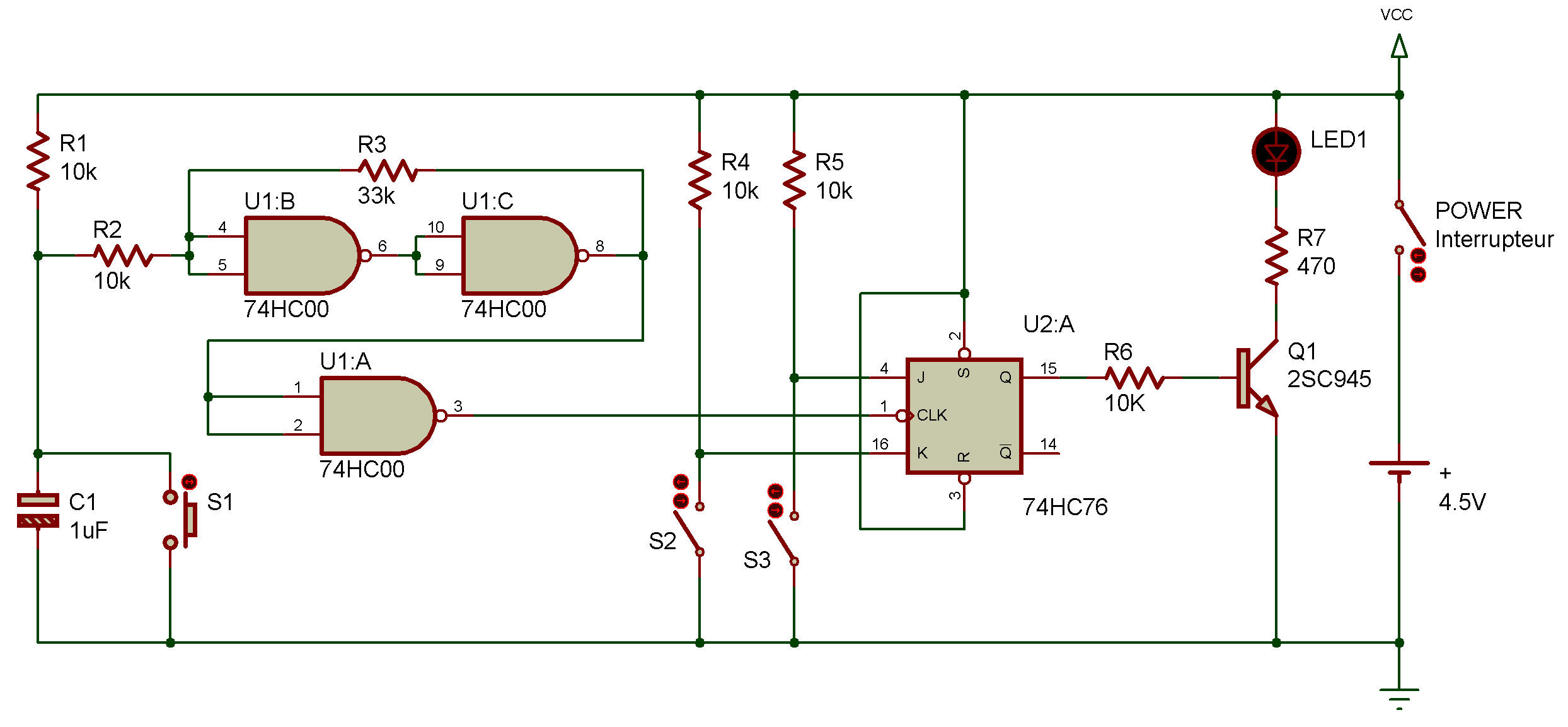
In project Transistorized toggle flip-flop, you saw how a flip-flop circuit can be "toggled" so that we can have additional control over it. You can see by the schematic that you'll provide the clock signal for this circuit each time you press S1. The signals for the J and K inputs are provided by S2 and S3.
After you build this project, turn power ON and press S1 a few times. You'll see LED 1 go on and off.
Now press S3. While you pressing it, press S1 a few times. What happens to LED 1 ?
Release S3 and press S1 again. Is there any difference in what LED 1 does?
Now press S1 while pressing S2 several times. What does LED 1 do now?
Release S2 and press S1 again. What happens to LED 1 ?
As you may have figured out, if both the J and K inputs are 1, the flip-flop sets and resets each time you press S1 (which inputs a clock signal).
This means LED 1 goes on and off. But if you press S3, this makes LED 1 goes out when the flip-flop reverses a clock signal and stays out. When you release S3 and press S2, the J input is 1 while the K input is 0. This means LED 1 lights with a clock signal and stays lit.
Time to put on your thinking cap - can you think of some of the interesting things and could be done of you used different types of multivibrator circuits for the clock, J and K inputs? Try whipping up some circuits to see if you're right.

![]()