Divide by 4 counter
7400, 7476

or

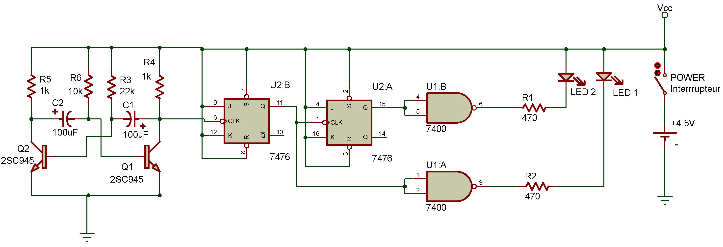
Here's a counter circuit that can count up to four. (Gee, these Projects must be getting smarter as we go along!)
Like our previous counters, it uses flip-flops, but a special kind. Can you guess which?
As you can see in the schematic, this Project uses a NAND multivibrator to set up the pulses which are counted.
When put the power ON, both LEDs 1 and 2 will blink on and off, After some blinking, you'll begin to see a pattern develops. First LED 1 comes on, then LED 2a then both on, and then both off, 1, 2, 1 and 2, off... both LED's will blink on and off in this sequence.
Did you guess which type of flip-flop we'ie using in this Project? It's a toggle flip-flop, which we first met back in Project Transistorized toggle flip-flop. You can see from the schematic that the Q output of the first flip-flop serves as the clock input for the second flip-flop, meaning that this counter circuit is ...

Back in Project J-k toggle flip-flop we saw how-"master and slave" flip-flop arrangements worked. This is the same arrangement used in this Project The first flip-flop controls the operation of the second. Try tracing the input of the multivibrator through the flip-flops to see how the LEDs are turned off and on!.
