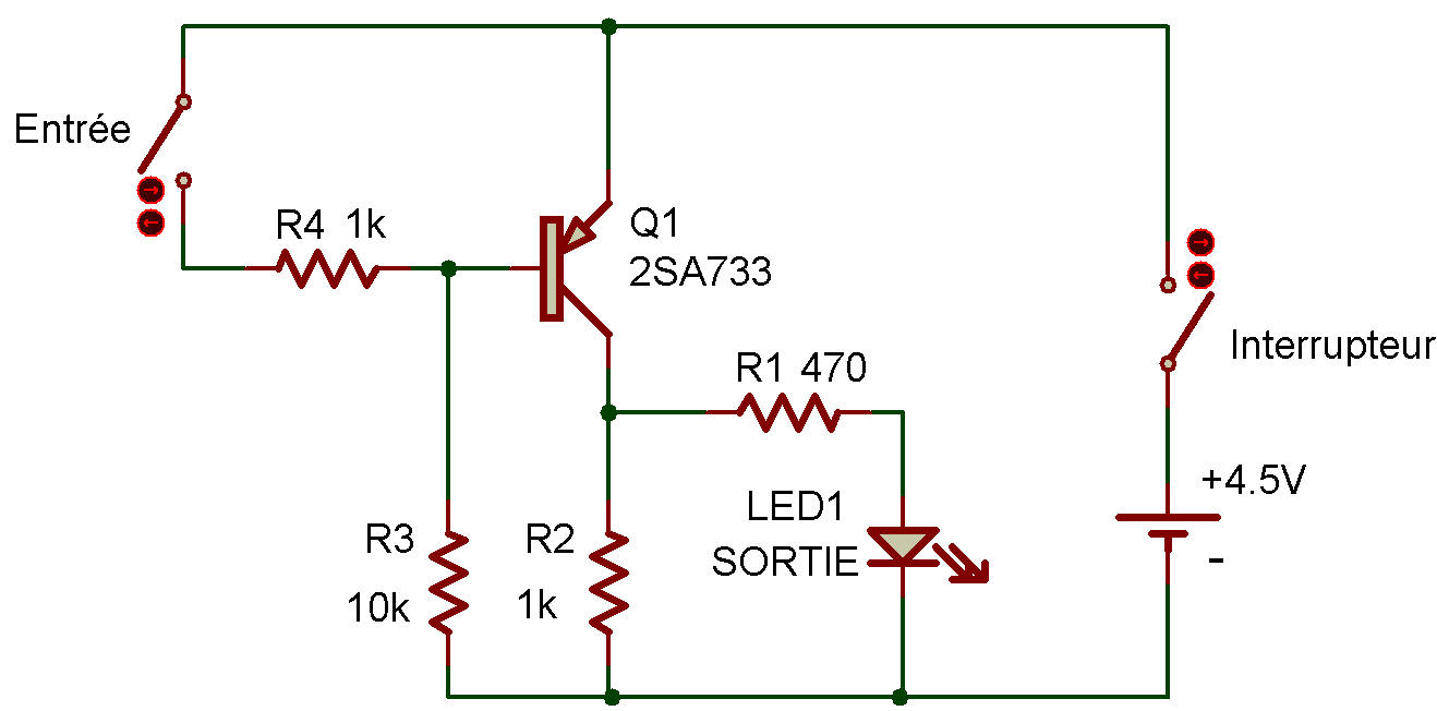
RTL inverter
So far we've played with logic circuits made up of switches to show how various circuits such as NAND, OR, AND, etc, work.
Of course, digital circuits in the real world aren't made of switches— they use transistors, diodes, resistors, etc.
Just like other electronic circuits. This Project will let us take a look at a "real" all-electronic digital circuit. This circuit is another version of the inverter we first saw back in Project An inverter circuit. It's called an RTL inverter because it makes use of resisxor-iransistor logic, It's called that because the circuit is made of resistors and transistors, logically! (Sorry about that.....but we couldn't pass up that pun!)
When you put ON the power, LED 1 will be lit (and that means the output is 1), Since you're not pressing the Key, the input is 0. Press the Key and you'll make the input 1. LED 1 immediately goes out, making the output 0.
That's what an inveter does - reverses an input.
This circuit uses a transistor's ability to function as a switch (you might want to look back at Project Transistors as Switches in case you've forgotten).
Of course, we don't have to always press the Key to use a transistor as a switch - we could use the output from another circuit, couldrft we? (Of course we could!)

![]()