RTL OR gate
It's easy to make an OR gate using resistor-transistor logic. This circuit is an all-electronic version of Project OR gate.
As you build this circuit, set the Select Switch to B. When you finish the wiring, put the power ON. Press the Key and watch LED 1. What happens?
Now release the Key and set the Select Switch to A. Does anything happen now?
While the Select Switch is at A, press the Key again, Is there any change?
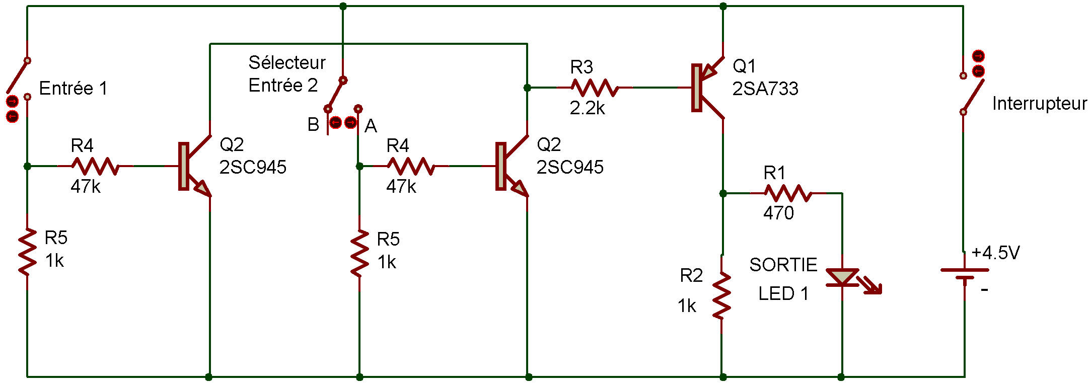
You saw that this circuit behaves just like the OR gates in Projects OR gate and Three-input OR circuit. You can see why it doss so by looking at the schematic.
When you press the Key or set the Select Switch to A, you let current flow to the base of one of the two 2SC Transistors. This lets the 2SC Transistor operate, and in turn this causes the 2SA Transistor to operate and light the LED. And the 2SA Transistor will operate if both 2SC Transistors are operating.
As you probably suspect, we seldom use actual switches (like the Key in this Project) with OR gates. Another circuit like a multivibrator can supply the input signal to turn on OR gate on or off (or make it 0 or 1, or make it high or low... well you know what we mean!).

![]()