
Logic Tester
NE5532
You know that digital circuits produce high or low (H or L) outputs (1 or 0). Now we're going to make a logic tester that shows 1 for high level (H) and 0 for low level (L) on the LED display.
Slide the switch to position OFF and assemble the circuit. When you finish the wiring, turn on the power by sliding the switch to position ON.
The number 0 is on the display because the test terminal (terminal T1) is at low level when no input is applied.
Connect the test terminal to terminal + to apply a voltage. The display changes to 1.
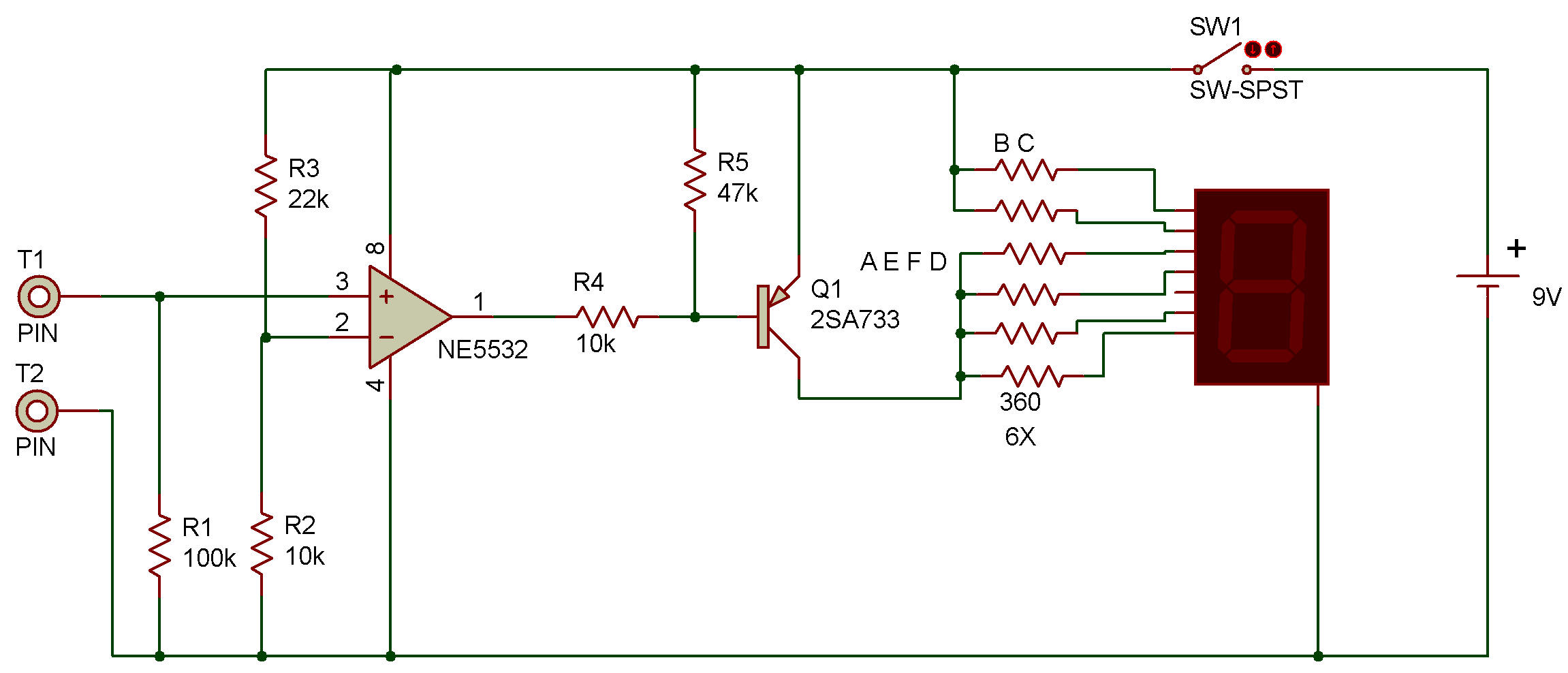
Look at the schematic. The dual operational amplifier works as a comparator. A reference voltage of about 3 V is applied to its (—) negative input terminal. When the input applied to its positive (+) terminal is higher than this reference voltage, the comparator's output level becomes high, turning off the transistor Q1. Segments a, e, f, and d of the display turn off, leaving 1 on the display.
![]()