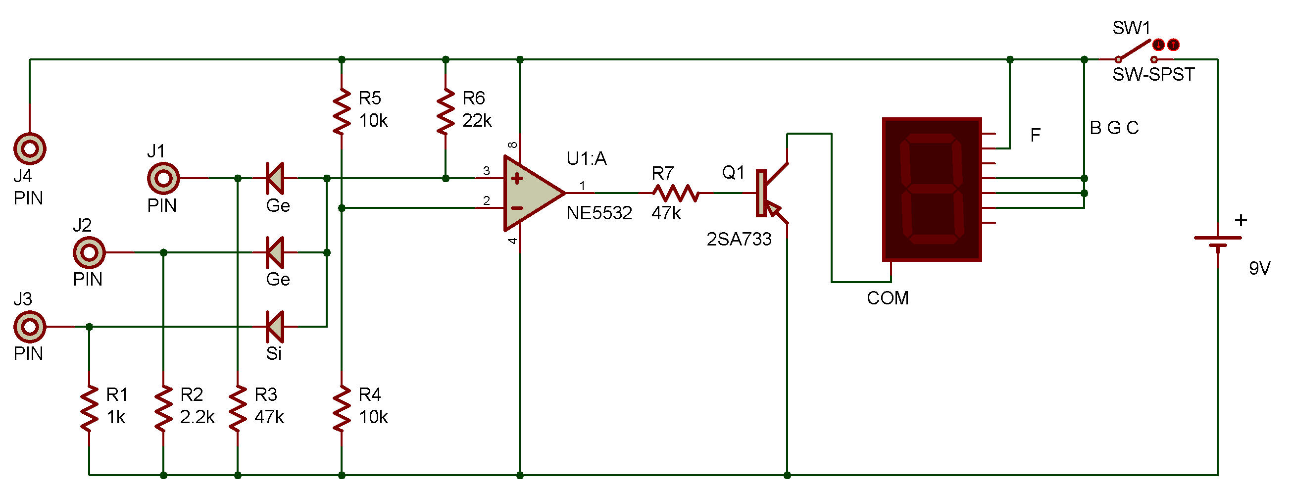
Three-Input AND Gate Using Operational Amplifier
NE5532
Who says the operational amplifier can't be used to make a digital circuit?
Here, we use one to make an AND gate.
The LED display is the output device.
If it displays nothing, at least one of the output signals is logical 0 or low; if it displays H, they are all logical 1 or high.
When you complete the wiring, turn on the power by setting the switch to position ON.
The LED remains dark.
Terminals J1, J2, and J3 are the input terminals.
These terminals are connected to the negative (—) terminal, so they do not cause the LED to light.
Terminal J4 is connected to the positive ( + ) terminal, so it is the logic 1 terminal.
When you connect terminals J1, J2, and J2 to terminal J4 in various combinations, you see that the LED lights and shows Η only when terminals J1, J2, and J3 are all connected to terminal J4 - logic 1.

![]()