Voice Level Meter
NE5532
In this project we make a voice input level meter.
The brightness of the LED in this circuit changes according to the level of voice input that comes from the microphone (the earphone).
Since voice levels change very quickly, the brightness of the LED should also change very quickly.
In order to show the highest voice input levels, we use a circuit called a peak-level hold circuit.
This allows the LED to hold a certain brightness after it reaches peak strength, rather than turning off immediately.
Set the switch to position ON after completing the wiring.
You will use the earphone as a microphone. Speak loudly or blow strongly into the earphone.
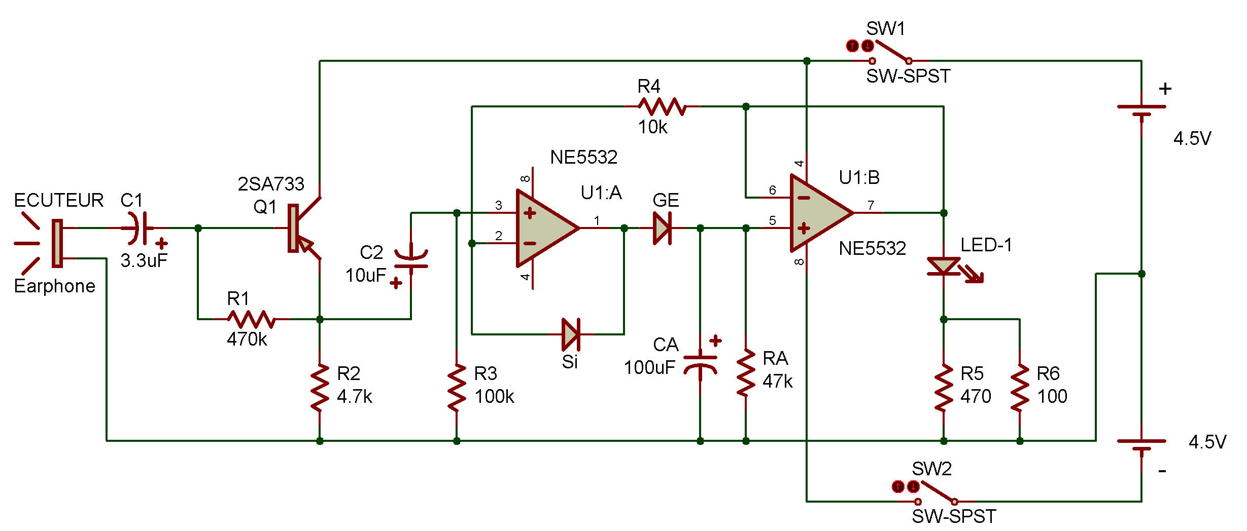
You can see the LED get brighter temporarily and then gradually grow dimmer. Look at the schematic.
You can see that the signal from the earphone travels through the PNP transistor and then becomes the positive ( + ) input for the first operational amplifier.
The output of this operational amplifier is stored at the 100μF capacitor.
The voltage of this capacitor lowers as it slowly discharges through the 47K ohm resistor.
As the voltage decreases, the LED grows dim.
At the same time, the voltage that lights the LED flows to the negative (—) input of the first operational amplifier.
The first operational amplifier compares this voltage with the input signal from the earphone; when the input signal is larger, it charges the 100μF capacitor, when the input signal is smaller no output is produced.
You can change the brightness of the LED by changing resistor RA (47K ohm) or the capacitor CA (100μF).

![]()