THE FM ANTENNA
The secret to getting a good range with low power is providing a good transmitting antenna.
In addition, a good ground-plane is also needed.
The batteries are normally used to provide a ground plane and that's why the leads to the battery must be kept as short as possible. 5cm of battery lead can reduce the output to half.
Connecting the battery directly to the board can double the output. Adding a thick ground-plane to the PC board can also help considerably.
But, of course, it is the antenna that does most of the work. Since we are transmitting at about 100MHz, the wavelength of the signal is 3.3 meters and a full wave antenna would be 3.3 meters long.
It is often quite inconvenient to use a long antenna, so here are some alternatives.
Obviously you can use a shorter antenna, but as you reduce the length, the range reduces. Surprisingly, it does not decrease greatly when the antenna is reduced to "half-wave".
Many of the kits on the web are supplied with an antenna 30cm long to reduce the range and make the transmitter somewhat legal.
But this is not what building and testing is all about. The hobbyist wants to know how far he can reach with the transmitter he has made.
Placing the antenna on top of a cupboard is a good choice. It provides height and you can stretch the antenna to its full 1.65m length.
The receiving antenna on a radio must also be horizontal and somewhere at the front or back of the transmitting antenna. If you require omnidirectional radiation, (radiation 360°) the antenna must be upright (vertical).
The receiving antenna must also be vertical and can be anywhere in the 360° radius. We are not going into the complexities of different radiating patterns of antennas but here is one suggestion for an improved antenna.
It is called a DIPOLE.
You can get a closed dipole, folded dipole and others but ours is a simple design.
THE DIPOLE
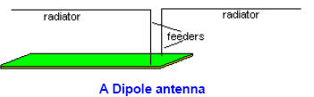
If you want to transmit in a particular direction, you can fit a dipole antenna.. This is simply connecting one wire to the antenna output and another wire to the 0v rail and stretching each out horizontally in the opposite directions.
These are called RADIATORS and if you want to have them higher than the transmitter, the two wires run parallel to each other and very close. These are called FEEDERS. Here is a diagram of a DIPOLE:
This will produce an antenna over 3 meters long and the transmission will be greatest at the front and back. You ca n experiment by shortening both wires and do a field test to determine the range.
Adding a wire to the 0v rail increases the output as it gives the circuit a good ground plan e and allows more signal to be pushed out the "antenna point" (on the circuit).
The feeder wires do not radiate a signal because each line is clos e to the other and the signals cancel. That's why the feeder wires should not be too close - they lose energy and if they are close together, they lose more energy and they should be short as possible.

![]()