FM 3 TRANSISTOR CIRCUITS
THE TANK CIRCUIT AND "Q"
Before we go to 3-Transistor circuits, there is one factor that needs mentioning. It is the most important part of the circuit.
The TANK CIRCUIT. This is the coil and capacitor in the collector of the oscillator transistor. Even though these two components are classified as "passive" - and do not amplify, when they are connected in parallel, they form a circuit known as a TANK CIRCUIT and actually produce a waveform that is larger than the supplied voltage.
These two components set the frequency of the circuit and when they are operating correctly, the output will be a maximum. A lot of experimentation has gone into the size of the inductor and by making it 3-4 times longer than the diameter, using the thickest wire possible and spreading the turns, the inductance will provide the maximum amount of energy to pass to the capacitor.
Not only does the value of inductance and capacitance have to be correct to achieve the desired frequency, but the energy from the inductor must match the energy from the capacitor, to get the maximum output. All this is done to a chieve a high output and when a tank circuit is lightly loaded it will oscillate at one and only one frequency.
When this happens and when we measure the output and compare it to the supply voltage we get a value called the "Quality Value" or "Q" value. This value is not known for these circuits but the result of a good tank circuit can be see n by testing the circuit with a Field Strength Meter or simply detecting the output of the bug at a distance.
3 transistors cicuit
Three transistors will give a wide range of designs.
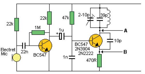
Here are 6 circuits showing how to connect a buffer stage to an oscillator. But first we need to show the buffer can be connected to the oscillator stage via point A or point B.
Point A has a higher amplitude but since this point is a high-impedance point, any energy taken from this point will affect the amplitude of the oscillator.
Point B a low-impedance point, but has a much lower amplitude.
Thus we have a decision to make. I prefer the collector take-off point as it has a larger signal and this signal can be passed to the buffer stage via a small capacitor to fully drive the buffer transistor.
The capacitor will actually convert a large signal with low current into a smaller signal with higher current. This is one of amazing things a capacitor will do. You may think point A is a low impedance point as it is just a fraction of an ohm away from the positive rail.
But the inductor (coil) is creating a voltage and waveform at point A and if any load is applied at this point, the waveform will decrease, because the inductor does not have much "strength" to produce the waveform. It does not have much strength because the transistor is being driven very lightly and the stage is only consuming very little current.
To understand this more clearly, you need to know how the stage works so you can see how delicate the circuit is.
When the power is applied, the circuit starts to operate due to the 47k bias resistor on the base.
The next point to note is the base is held rigid by the 1n on the base. This capacitor has an impedance of less than one ohm at 100MHz and you can consider the 1n as a 2v battery with an impedance of 1 ohm or a one ohm resistor sitting on top of a 2v battery.
In any case the base is held very rigid by the 1n.
Now we come to understanding how an NPN transistor "turns on." It can be turned on in two ways.
The emitter can be held rigid and the base can be raised to 0.6v and if the voltage is raised slightly more and the base is fed with current, the transistor will conduct and current will flow in the collector-emitter circuit. This is the case with the transistor in the audio stage. The emitter is held rigid and the base is fed with current, once the base is above 0.65v.
The other way to turn on an NPN transistor is to hold the base firm and lower the emitter. Once the emitter is lower than the base by 0.65v, the transistor turns on and if the emitter is lowered slightly more, the transistor turns on more. This may be difficult to visualize, but this is occurring in the oscillator stage.
Let's advance a few cycles and see what is happening. The transistor turns on and the collector pushes the top of the 10p capacitor towards the emitter. The energy in the capacitor gets converted to a small voltage and larger current.
We said before, that a capacitor can do this. The small voltage pushes the emitter lower and this turns ON the transistor. The result is a little bit of energy is pumped into the capacitor in the tuned circuit.
At this instant, the coil does not get energy from the transistor because a coil resists any quick flow of current into it and it acts like a very large resistor.
The energy in the 10p is now spent and the transistor turn s off slightly.
The energy from the capacitor in the tuned circuit passes to the coil and when the capacitor can no-longer keep the flux in the coil increasing, there comes a point where the flux starts to collapse.
This flux produces a voltage that is larger than before and is opposite to the previous voltage. This is one of the amazing things of a coil and capacitor in parallel.
The voltage at the lower end of the coil-capacitor combination is higher than the supply and this raises the top plate of the 10p capacitor. This rises the voltage on the emitter and turns the transistor off completely. This allows the tank circuit to produce its amazing HIGH VOLTAGE without the transistor loading the circuit.
But he coil/ capacitor is a very delicate arrangement and it is producing the high voltage at very low current as it is converting the original low voltage small current into high voltage very low current. If we put a load on the circuit at point "A" we will reduce the voltage and may freeze the circuit.
The following 9 circuits show different ways to "tap-off" the waveform and amplify it in a stage called a BUFFER.
The BUFFER converts a HIGH IMPEDANCE signal into a LOW IMPEDANCE signal as the antenna is commonly referred to as a 50 OHM LOAD. The simplest buffer is shown in the following circuit. It is a common emitter stage with a resistive load.
1. STABILITY

A BC 547 transistor is not very good at amplifying at 100MHz. The circuit above does not give a range greater than the 2-transistor version, but the stability is much greater. The antenna can be touched without the bug drifting off frequency.
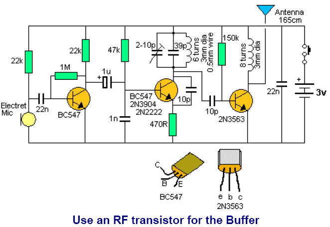
2. INCREASED RANGE
To increase the range, the output must be increased. This can be done by using an RF transistor and adding an inductor. This effectively converts more of the current taken by the circuit into RF output. The output is classified as an untuned circuit.
3. MORE RANGE
More output can be obtained by increasing the voltage and adding a capacitor to the output to tune the buffer stage. The 5-30p must be adjusted each time the frequency of the bug is changed. This is best done with a field strength meter.
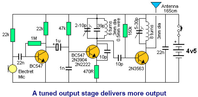
The 2N3563 is capable of passing 15mA in the buffer stage and about 30% is delivered as RF. This makes the transmitter capable of delivering about 22mW.
The 2N3563 is also available as PN2563 where PN signifies "plastic package."
These (this) transistor is not a POWER TRANSISTOR. It is classified as a SMAL L-SIGNAL TRANSISTOR and even though the pdf indicates the collector current is 50mA, you will notice all the specifications are provided at 8mA!
That's why we have allowed a maximum current of 15mA for our calculations.
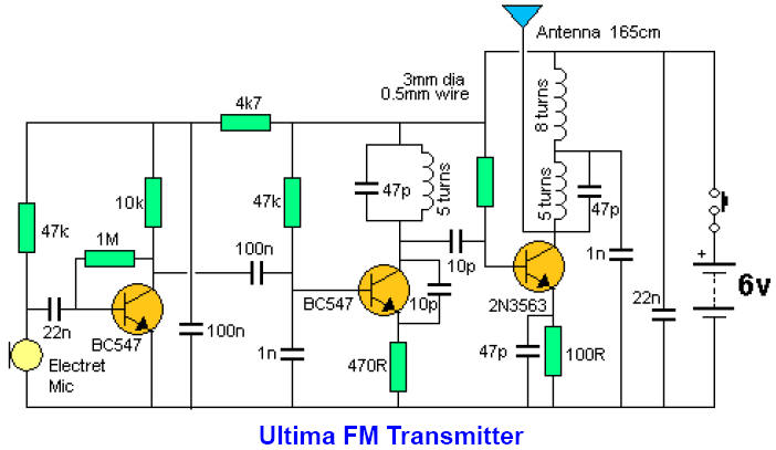
ULTIMA FM BUG - 1km TRANSMITTER
It has a range of 1km using a 6v supply.
4. DIFFERENT COUPLING
We have already mentioned the fact that a capacitor can convert a large waveform with low current into a small waveform with large current. The following circuit taps off the inductor at a point of low amplitude to put the least load on the tank circuit.
The coupling capacitor has been increased to transfer enough energy at low amplitude. This coupling has exactly the same result as shown in circuit 3. Circuit 3 is preferred as it is easier to connect to the collector than tap the inductor.
5. A PNP BUFFER
A PNP transistor can be used in the buffer stage, but as we said before the BC557 is not as good as an NPN transistor, when operating at high frequencies.

6. WASTED POWER
The following circuit (from the web) takes 30mA. This is wasted current.
As we said before, any voltage above 4.5v is excess and any current above 12mA for this type of circuit is excess. A BC557 cannot deal with any more than 5mA collector-emitter current. Any more than 5mA is wasted. That's why you need an RF transistor in the output.
7. EMITTER TAP
The following circuit taps the emitter of the oscillator stage. We have already explained the collector or the emitter can be tapped and produce about the same results.

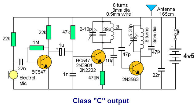
8. CLASS "C" OUTPUT
The following circuit uses no biasing on the output transistor. It gets all the energy to activate the base from the oscillator stage.
While this is possible, the amount of energy needed is very large and the oscillator cannot provide enough energy to fully drive the output stage. For the cost of a fraction of a milliamp, it is better to bias the output transistor and get a much-greater output.
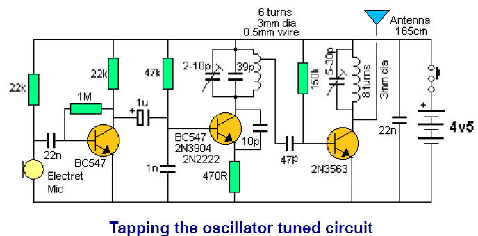
9. ADJUSTABLE OSCILLATOR COIL
To make a circuit more compact or cheaper (of if you don't have a trimmer), the oscillator coil can be adjusted by stretching or compressing. When the coil is stretched, the frequency increases. The buffer circuit has to be adjusted too, to get the greatest output.

A GOOD CIRCUIT
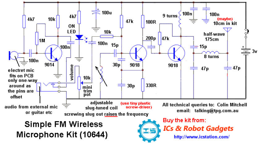
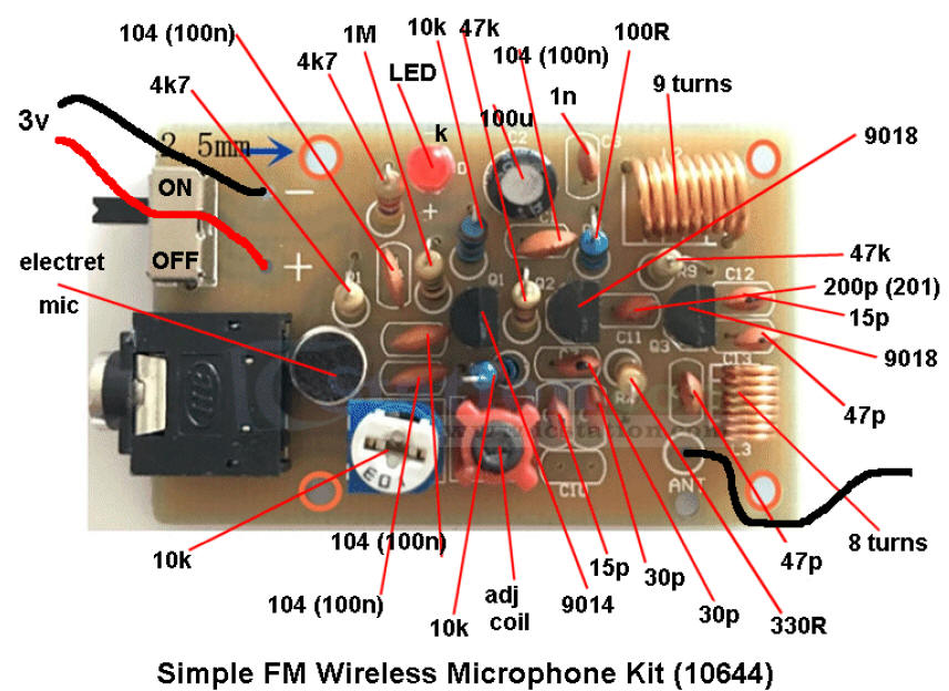
The oscillator in this project uses a SERIES TUNED CIRCUIT circuit made up of an adjustable slug-tuned coil and 15p capacitor.
The circuit works very well and the cost of the project is very small from the supplier shown below the circuit. Only a few points to note:
The kit of parts does not include a battery holder or antenna wire or solder.
The PCB is possibly nickel plated and not solder-tinned and it is slow to make each solder-connection.
The lands are very small and you need a very fine tipped soldering iron to complete the assembly. 3v is the best supply voltage as a higher voltage will overload the oscillator transistor and cause spurious transmission on different parts of the band and may interfere with other stations.
The effectiveness of the "pi" filter on the output to match the impedance of the antenna to the output transistor is very debatable.
The two 47p capacitors should be adjustable because, when you adjust them, the energy delivered to the antenna increases enormously.
In addition, the coupling capacitor is only 15p and this is the major limitation of the amount of energy reaching the antenna. Compare the 15p with the 200p coupling the oscillator to the buffer transistor.
The 200p is only 10 ohms and when you consider the base of the buffer transistor is very low in the way of "resistance," the 200p should be more like 47p.
The circuit is a Colpitts oscillator because it uses and un-tapped coil.
The circuit starts by the 47k delivering current to the base of the transistor.
The top 30p charges (and the 15p charges) and when the base is 0.6v higher than the emitter, the transistor starts to turn ON. Current flows through the 330R and a voltage is produced across this resistor.
The two capacitors keep charging and the transistor turns on more and more. It come to a point where the current supplied by the 47k will not turn the transistor on any harder.
Normally the transistor would stay in t his condition but the 15p and coil form a circuit called a SERIES TUNED CIRCUIT. But it is what happens with the TUNED CIRCUIT that creates the second half of the cycle.
The tuned circuit has been given a pulse of energy and the capacitor has charged because the inductor has produced a back-voltage during this time (called the charging current) and this has produced magnetic flux that cuts all the turns of the coil and produced a back voltage that only allows a very small current to flow through the coil.
The result is the voltage appearing across the two components will mainly appear across the capacitor. We now come to a point where the voltage on the base is as high as it will get and the 15p is charged to a potential that will not increase.
This means the charging current through the 15p will decrease and the magnetic flux from the coil will start to collapse. As it collapses, it produces a voltage in the turns that is of opposite potential and this pulls the 15p down towards the 0v rail.
This reduces the voltage on the base and the transistor starts to turn OFF. This action continues until all the magnetic flux is converted to voltage.
The 15p cannot pull the base any lower and it is always fighting against the 47k. A point comes when the current from the 47k starts to make the base rise again.
The competes the two halves of the cycle. It is the time taken for the inductor to lose its energy that determines the duration of the cycle.
The 15p also has an effect on the timing. Some of the magnetic flux is absorbed by the ferrite core and this changes the timing and thus the frequency at which the circuit operates.
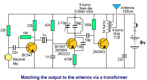
To create an output transformer for circuit 6 above, wind 14 turns onto the slug and 4 turns over the 14 turns.
The ferrite core will do two things. Firstly it provides a high amount of energy to pass from the primary winding to the antenna. And secondly it will prevent harmonics passing to the antenna.
The only way to prove the effectiveness of the transformer is with a field test and the range increased nearly 100%, over the tuned output design in circuit 9.

The photo above shows the 14 turns wound on the ferrite slug and 4 turns wound over this winding. Remove the enamel from the 4 ends and solder the leads as shown on the circuit diagram.
It does not matter which way the winding is wound and you can experiment with adding more turns to the primary or removing turns from the secondary to get the highest output.
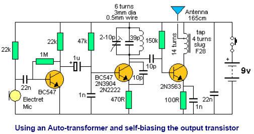
A slight improvement to the design is to make an auto-transformer. The circuit likes the fact that some of the current and voltage is already flowing in the "secondary" of the auto-transformer and it simply adds to this.
The other improvement is to make the output transistor self-biasing by including an emitter resistor. This allows all the transistors in a batch to take approximately the same current as the gain of each transistor will determine the quiescent current, with high-gain devices taking more current.
The addition of the 100R will reduce the spread in quiescent current. The output of the stage will not fall since the impedance of the 1n at 1 00MHz is very small.
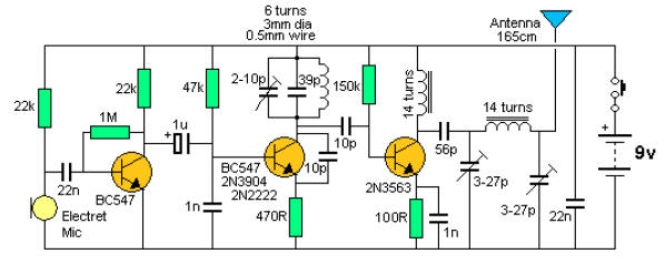
A transformer is the best way to couple the output of the transmitter to the antenna but capacitors and inductors in an arrangement known as "pi," "T," or "L" coupling can be used.
This is when you take advantage of the fact that a capacitor can convert a high-voltage at low-current into a low-voltage at high-current and an inductor has a higher impedance at high frequency.
It will reduce harmonics and the capacitor will provide a higher current to produce higher electromagnetic radiation. This is how a high impedance (resistance) is converted into a low impedance.
This type of coupling has been added to the following circuit. This is actually highly effective but the components must be adjusted accurately to have the greatest effect. In addition, the frequency of the oscillator cannot be changed without having to re-align the output.
The following circuit uses three parallel tuned circuits to couple the output of the transmitter to the antenna.
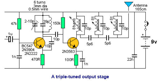
Don't forget, you are trying to connect a 4k impedance of the circuit to a 50 ohm load.
The first tuned circuit is in the collector of the output transistor. It is very similar to the " inductor" circuit above except the capacitor across the coil will improve the performance of the circuit enormously when the slug in the coil is adjusted. But this arrangement has a disadvantage.
The output will only perform to its best on a particular frequency (via the 10p capacitor and 8t coil) when the slug in the coil is turned to produce a maximum output.
The 2-1 0p air trimmer in the oscillator stage cannot be adjusted without re-tuning the output stage and this limits the versatility of the circuit.
However considerably more energy w ill be delivered to the antenna when the 3 tuned output stages are adjusted for maximum output.
The signal from the first is tapped off with a 5p6 capacitor to the second "TUNED SECTION." This is the coil and capacitor in parallel. The second "tuned section" is then adjusted to give maximum output.
The energy is then "tapped off" to a third tuned stage to which the antenna is connected. If you are prepared to have a fixed-frequency circuit, this arrangement is excellent.
It does three things:
1. It separates the output stage from the antenna, You can touch the antenna without affecting the frequency.
2. It converts more of the energy at the output stage, than previous circuits, and
3. It matches the 4k of the output stage to the 50 ohm impedance of the antenna .
Of course there is a lot of very complex mathematics that can be applied to working out the value if the components needed to interface between the output stage of a circuit and the antenna.
But nowhere will you find the "reason" why the components convert the signal from one impedance to another.
For the first time we have told you: "it's the squeezing action of the capacitor, converting a high-voltage, low-current into a low-voltage high-current." This produces the effect of converting a high impedance into a low impedance.
An inductor can convert a low-voltage high-current into a high-voltage, low-current by the collapsing magnetic field producing a very high voltage and this is how we convert a low impedance into a high impedance.
THE COIL
Whenever you see a coil in a circuit, magic things can happen.
This is due to the phenomena of the coil producing a higher voltage (in the opposite direction) when the applied voltage suddenly stops.
And when you see two windings (or one winding with an auto-transformer), you do not know what output you will get without knowing all the details of the transformer and actually seeing it in action.
The most effective oscillator coil has the dimensions of being at least twice as long as its diameter. In the following photo, the small coil is the TANK COIL and the larger coil (called an inductor) is on t he output.
The diameter of the small coil is too large. It has been wound on a 5mm drill. It should be wound on a 3.5mm drill and the number of turns increased from 4 to 6. (The turns are counted at the top of the coil.)
This will improve the "Q" of the coil. The inductor can also be reduced in diameter.

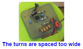
The second image shows a 4-turn coil with the turns spaced too wide. The maximum spacing is the thickness of the wire.
When the turns are spaced very wide, the "Q" of the coil is reduced and the performance of the circuit reduces.
When the length to diameter is 2:1, it allows the maximum amount of magnetic flux surrounding the coil to collapse back and cut the turns of the coil.
When designing a coil, here are the four most important features:
1. The most important feature is getting the length-to-diameter to be at least 2:1
2. The next improvement is choosing the core material. Air has a value of 1 at all frequencies. Ferrite (F29 material) will have a value of about 3 at 100MHz. This means the number of turns can be reduced to achieve the same inductance, and the coil will be less prone to external influences such as metal objects, but we have not found the output to be any better than an air coil (in any of the FM transmitters we have designed).
3. The next critical factor is the spacing of the turns. The best is close-spaced but they can have a small gap (the width of the wire) and the coil will still be effective.
4. The gauge of the wire is not particularly critical however wire thinner than 0.25mm will vibrate and produce microphonic sounds. 0.5mm wire is the maximum you need. Thicker than 0.5mm is not needed.
0.1uH COIL
On some circuits you will find a value of 0.1uH (100nH) for the coil.
If you buy a ready-made inductor of this value, the circuit may work or it may not. The reason is the coil in the TANK circuit must have a high value of "Q" to get the greatest range.
To achieve a high Q, the coil should be hand-wound as shown in the notes for the circuits. A ready-made inductor will be many turns of very fine wire and will not be in the ratio mentioned above.
The wire will also be too fine. In. In addition, a hand-made coil can be adjusted by stretching the turns.

![]()