FM Transmitter
They transmit on the FM band in the range 88MHz to 108MHz. Most of them can be adjusted to transmit above or below the band and you need a radio that will pick up these frequencies, to detect them.
Since the FM band is almost entirely filled with radio stations, we will be providing details on how to adjust a radio so it will scan EITHER above the band or below the band.
Most radios can only be adjusted 10MHz above or below but this will be enough to provide a "blank" space for your transmitter. FM transmission pro vides perfect quality and when one of these transmitters is used in a house and received on a good quality radio, you cannot tell if the person is actually talking in the next room or via an FM link, through a radio.
This means all the FM bugs have the same perfect audio, but some circuits will detect fainter sounds and others will transmit further.
Some circuits can be handled without drifting off frequency and others are designed to be very small or fit on top of a 9v battery. By building these circuits you will learn an enormous amount about high frequency, audio and getting the maximum output with the least current.
It will add a number of "building blocks" to your understanding of electronics. Before I start, there are two things that particularly annoy me.
The first is a circuit diagram with C1, R1 etc and a parts list identifying the values. Circuit diagrams like this are obviously drawn by a non-electronics person.
The whole concept of looking at a circuit diagram and seeing the values gives the reader an indication of how each section will work.
A section may be operating very lightly with high value components or it may be working very hard with low value components. The whole idea of providing a circuit diagram with marked components is to give the reader an immediate understanding of how the circuit is operating.
The second thing that annoys me is the labelling of parts on a PC board as R1 , C1 etc.
Again, the board has been designed by a non-technical person.
Why design a board without component values?
Do they think the values will change?
How can you assemble a board without referring to a circuit diagram?
The whole purpose of well-designed PC board is to build it without referring to any other data. Keep this in mind when designed your own boards.
Also, don't name your boards "A51/834- 2." Give then a name you can remember or one that refers to the application it will perform.
Why use 1.5v?????
Transistors do not operate very well below 0.9v and the collector load resistor needs a small voltage so it can perform its task (the same applies to an emitter resistor) and thus the lowest voltage for a circuit is 1.5v.
If only a single cells is used, there is no allowance for a voltage drop as the cell becomes depleted. Always use 3v as the lowest supply voltage.
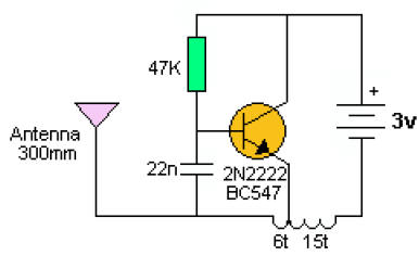
THE SIMPLEST CIRCUIT
The following circuit is the simplest FM circuit you can get. It has no microphone but the coil is so MICROPHONIC that it will pick up noises in the room via vibrations on a table.
The circuit does not have any section that determines the frequency. In the next circuit and all those that follow, the section that determines the frequency of operation is called the TUNED CIRCUIT or TANK CIRCUIT and consists of a coil and capacitor.
The transistor and components surrounding the tuned circuit simply keep the tuned circuit operating at its RESONANT FREQUENCY.
This circuit does not have this feature. The transistor turns on via the 47k and this puts a pulse through the 15 turn winding. The magnetic flux from this winding passes through the 6 turn winding and into the base of the transistor via the 22n capacitor.
This pulse is amplified by the transistor and the circuit is kept active. The frequency is determined by the 6 turn coil. By moving the turns to gether, the frequency will decrease.
The circuit transmits at 90MHz. It has a very poor range and consumes 16mA.
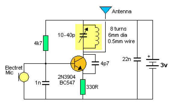
THE SIMPLEST BUG
A ONE TRANSISTOR CIRCUIT
The next circuit uses a TUNED CIRCUIT or TANK CIRCUIT to create the operating frequency. This is clearly shown in the diagram.
For best performance the circuit should be built on a PC board with all components fitted close to each other. The photo below shows the circuit using a coil etched on the board.
This type of coil is totally unsuitable. It does not have a high "Q" and the range is very poor. The board cannot be touched as the capacitance of your body causes the circuit to drift. A wound coil will improve the stability considerably. See photos below for the details of a wound coil.
THE COIL
I have particularly avoided mentioning the actual value (inductance in microhenry) of the coil because it is less than 1uH and is about 0.65uH.
That is 65nH (65 to 80 nano Henry). A coil of this inductance will be very hard to measure on an inductance meter, but if you want to measure it, here is the secret:
Place a 1uH inductor on the inductance meter and read the value. Now add the 65nH inductor and the reading will increase to 1.65uH. But a few turns of wire and a few circles o f track work on a Printed Circuit Board will produce the same 65nH reading but the coil will produce a much better result in the transmitter.
This is all to do with a term called EFFICIENCY or "Q" of the coil and in the controlled conditions of these oscillators, the best coil will "deliver back" nearly 100% of the energy it is supplied.
This result in a waveform in the antenna of nearly twice the voltage of the supply.
The other secret in producing a good output is to have the capacitor and coil "match" each other. In other words, the energy delivered back from the coil is the same as the energy delivered back from the capacitor. That's why the capacitor should be 39p and the coil 5 or 6 turns. You can use 47p and a coil of 5 or 6 turns.
Stretching the coil reduces the inductance and this is how the two are matched together and produce a frequency somewhere in the region of 85MHz to 110MHz.
For 39p and 65nH the resonant frequency will be 100MHz from a calculator. But this may be different in a circuit due to the effect of the transistor. For 47p and 70nH the resonant frequency will be 88M Hz.
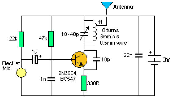
MORE STABILITY
If you want more stability, the antenna can be tapped off the top of the tank circuit. This actually does two things.
It keeps the antenna away from the highly active collector and turns the coil into an auto-transformer where the energy from the 8 turns is passed to a single turn.
This effectively increases the current into the antenna. And that is exactly what we want. The range is not as far but the stability is better.
The frequency will not drift as much when the bug is held. As the tap is taken towards the collector, the output increase but the stability deceases.
STEREO TO MONO
To combine two channels to a mono output, the following circuit can be used:
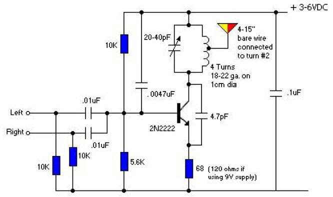

![]()