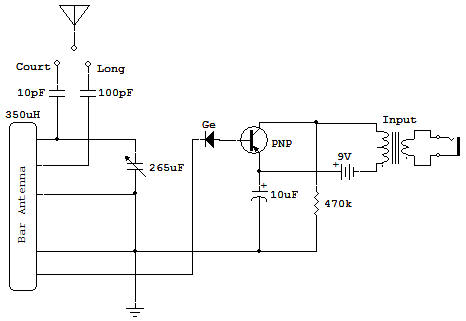
One Transistor Radio with Diode

The logical progression from the simple crystal radio on project Crystal Set Radio is to this one Transistor radio. The Antenna and tuning circuitry is the same as for project Crystal Set Radio. The changes are described here. (See project Crystal Set Radio for a description and suggestions about antenna systems. Recall that one compromise necessary in simple radios is that between the selectivity and sensitivity (or volume).
Because of the Transistor amplifier we may now take the RF signal from the tuning coil link. This link has only a few turns of wire around the ferrite core so transfer of power is low, giving decreased sensitivity, but this also causes less loading on the tank circuit so that selectivity is improved.
For this reason we can't expect as much improvement in volume as we can selectivity. Stations which could not be separated on the crystal set are easier to separate with this receiver. The Diode performs the same function of detection as in the crystal set except that now a very small Transistor base-bias current (about 20uA) is also passed through the Diode.
The effect of this small current is negligible as far as the function of the Diode is concerned. The 10uF Capacitor couples the ground side of the detector output to the Transistor without shunting (bypassing) the DC bias for the base of the Transistor.
The Transistor acts like a variable resistance between collector (C) and emitter (E), which is controlled by the amount of input signal between base and emitter (B-E). Assume an average resistance between C-E of about 22K ohms.
Current flowing around the circuit from Battery negative, to the Transformer, to collector and then from emitter back to the Battery positive is about 4mA (milliamperes). As the detected signal applied between B-E increases and decreases at an audio frequency rate, the 4mA of collector current also increases and decreases at this same audio frequency rate.
This change in current through the primary winding of the Transformer causes a voltage to be developed at the secondary winding for use by the Earphone.
The 470K Resistor supplies a very small current to the base of the Transistor to turn it ON a small amount. A Transistor is said to be OFF when voltage is applied between C-E but no current is supplied to the base-emitter junction, so no collector current is flowing. A Transistor which has base-bias current so that collector current can flow, is said to be ON.
For experimentation you may want to try different Antennas and Grounds, as before. Also, you should try shunting the primary winding with different Capacitors to see their effect on tone quality. Try the Earphone on the primary winding. If you want a pleasant surprise try replacing the Diode with a short circuit. Who needs a Diode when the Transistor can perform double duty!
