Radio signal monitor
This project is a modified version of the alarms NOT WAVE used by most AM radio stations. The modification is to provide a tone to indicate when the RF signal is present as opposed to when the RF signal is absent. A light change of a wire of the relay makes the change. The circuit is simple. Connect a good antenna. Tune across the width of the band and note the dial settings that cause the tone to the speaker. These are the settings where radio signals are present.
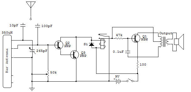
Use the 50K control as a sensitivity control. If set too low, some positions will not sound the alarm, and too high, may enable the circuit to respond to noise or fruity transistors.
The circuit uses transistors Q2 and Q3 connected as a Darlington amplifier. This arrangement results in extremely high current gain and high resistance to base entrance. For this reason, and because no base bias is provided, a detector diode is not necessary. The relay can be excited by these transistors. A silicon diode (Si) is supplied through the relay coil to absorb and direct the peak stop current relay.
The oscillator circuit is standard oscillator pulse transformer-type center tapped. Resistance of 47K provides the initial polarization base and the discharging resistor for the capacitor of 0.1 uF. The 0.1 uF regenerative torque reaction at the base and provides the downtime charge. The 100 ohm resistor provides a current drop to the base currents of Q1 and the collector.

![]()