Resistors in series
We've been using resistors in almost all of the Projects up to this point. But we've never mentioned exactly what resistors do in a circuit. Here's an experiment to let us find out. One clue to what resistors do is found in their name — they resist (oppose) the flow of electricity.
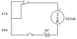
This makes them handy for reducing voltages down to a desired value, for example. Very often you'll see two or more resistors connected together in different ways in circuits. Notice in the schematic for this Project that the resistors are connected one after another.
You can see that the electricity will flow from one resistor to the other. This is called a series connection.
Set the Select Switch to B position (like the schematic) and then set the Control Knob to ON. You'll see the Meter pointer swing very far to the right.
Now look carefully at the schematic. What do you think would happen if the Select Switch was set to A? Are you sure of your answer?
Okay, then set the Select Switch to A and let's find out! The Meter doesn't swing as far to the left as it did at B. This is because when resistors are connected in series, the total resistance increases. To find the total resistance, all you have to da is add the values of the individual resistors.
Resistors, by the way, axe measured in a unit called the ohm, Larger resistors are measured in kilohms, which is often abbreviated simply as K. A kilohm is 1000 ohms. In our schematic, the two resistors are 33K and 47K. In series, they add up to 80K, or 80 000 ohms.

![]()