
Light Controlled Switch
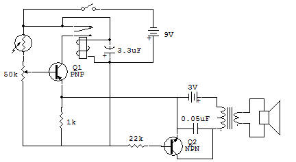
Here's a new study of switching possibilities. The relay is connected as a door buzzer that works all the time. The floor of the transistor Q1 functions as any other transistor stage did so to date. We'll call it a light control switch.
The output of this stage is used to supply the bias B-E to the stage Q2. The ON or STOP speed is controlled by the relay and is an audio system so that the output is heard in the speaker when the light hits the CdS cell.
The operation of the circuit is controlled by the switch Q1 operating at any desired level of light. Maybe can you think of a use for such a circuit, but it is here that because of its single switching action. Note that as the switch is closed and the control is set for the desired operation, the Q1 receives a base voltage.
However, the collector only receives periodic voltage pulses when the armature (the movable contact) of the relay moves to the coil and makes contact momentarily with the N.O. contact (normally open).
The current transmitter can then pass in the same brief periods of time. The emitter current of Q1 is provided as the emitter current of the stage Q2 so that it can also lead during the brief time of current pulses. This part of the emitter current of Q2 is the part that causes polarization B-F for the floor. This bias current (between E-B) puts Q2 ON for the current from the battery 3 volts can flow through the circuit and momentarily excite the speaker.
The capacitor of 0.05 pF prevents transient peak transformer to ruin the transistor Q2. This peak is produced by the sudden stop at the current transformer.
![]()