
Light Controlled Switch with CdS Cell
Now we'll go to another very common, and important category of circuits: Switching and Control Circuits.
Have you ever really stopped to think how much of our everyday life is affected by electrical and electronic controls? Think about if for a while, you'll be amazed to find out how common and important this type of circuit is to all of us. This project demonstrates the operation of a light controlled switch and provides the circuit explanation for the Electronic Candle in Transistor Section.
The circuit is similar to many light controlled circuits used in the home and in industry. Many yard and street lights are controlled by similar cells.
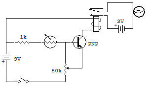
The 3V Lamp circuit is controlled by the contacts of the SPDT (signal-pole, double-throw) Relay. We have started out with the Relay contacts wired so that the light is normally OFF, but you only need to change the wire to make it normally ON. The Relay coil (field) is energized or powered by the 9V Battery through the C and E leads of the Transistor.
The Transistor acts like an open circuit between these terminals when it is OFF. A Transistor is OFF whenever it has no current flowing in its base lead. When sufficient current is caused to flow in the base lead, the Transistor is ON. When it is ON, the C and E leads of the Transistor act as though they are shorted together. This allows the current to flow to the Relay coil to energize the Relay. All Transistor currents must flow against the emitter arrow head.
The CdS Cell is a Resistor which appears as a very high resistance (virtual open circuit) in darkness, but in the presence of light its resistance decreases until in bright sunlight it is about 100 ohms, or so. This low resistance looks like a virtual short circuit or closed switch in circuits with normal resistance above a few thousand ohms or so.
Now, coupling the Transistor and CdS Cell together as shown in the Schematic diagram, we have effectively a CdS Cell "switch" controlling a Transistor "switch" which controls a Relay. With insufficient light, not enough current can flow into the base to turn the Transistor ON, or you can adjust the control to shunt (bypass) most of the current, keeping the Transistor OFF. When sufficient light is present, the CdS Cell allows enough current to flow into the base of the Transistor so it can turn on.
The 1K Resistor provides a little protection against excessive base current which could bum out the Transistor when bright light produces a very low CdS Cell resistance. Also the base current only has to be about 1/100 of the collector current to turn the Transistor full ON.
The Relay current is about 40mA, so to be full ON the Transistor only needs about 0.04mA of base current. To obtain this current the CdS Cell resistance only needs to decrease to about 2200 ohms (2.2k).
![]()