
Wheatstone Bridge
The purpose of this project is to consider the Wheatstone bridge circuit. This circuit for measuring resistances has been around for over 100 years. It must be a good circuit, to have survived so long. Virtually all instruments available today, for measuring DC resistances with extreme accuracy, are Wheatstone bridges.
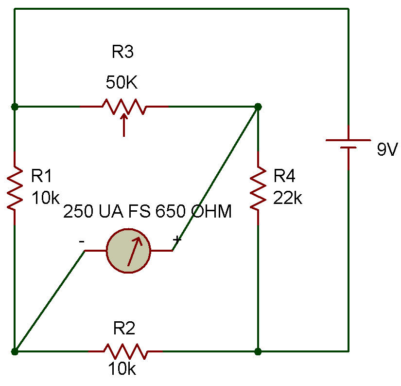
The circuit is made up of four resistances: R1, R2, R3 and R4, connected in a ring as shown in the Schematic diagram. The generator (a Battery) is connected across two opposite corners of the bridge. The detector (the Meter) is connected across the remaining two opposite comers of the bridge.
When proper resistances are used in the bridge, no current will flow in the Meter and the bridge is said to be "balanced". For all other combinations of resistances the Meter will receive current and thus indicate the in balance of the bridge.
The Control is usually calibrated directly in resistance. The intelligent use of this bridge circuit requires some simple mathematical relationships. In words, the relationship is: "balance is obtained when the ratios of adjacent arm resistances are equal".
In a formula this is:

is an unknown resistance to be measured, the formula is rearranged to solve for this resistance in terms of the other three known resistances. The formula is then as follows:
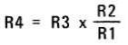
Notice that resistors R1 and R2 are in the form of a ratio in this final formula. For this reason these resistances are called the "ratio arms" of the bridge. In the bridge here R1 and R2 are equal in value so that R4 and R3 must also be equal for the bridge to be in balance.
When the bridge is in balance the Meter will be exactly on zero. Connect the circuit and notice that the Control must be set near center to obtain a zero Meter reading with the R4 value of 22K as shown. At this balance setting the control resistance is equal to the resistance of the 22K Resistor.
If the Control is calibrated by using a large number of known resistances for R4, you could use this as an ohmmeter like the circuit was intended.
You may want to try measuring other devices such as the CdS Cell, other Resistors or even between different leads of the Transistors. The resistances will have to be estimated, of course, unless you make up a calibration chart using known resistances for R4. Remember to adjust the Control for an exact zero meter reading to obtain circuit balance.
![]()