Accelerometer
This project demonstrates the operation of an accelerometer. The function of an accelerometer is to indicate when an object is increasing in speed or accelerating. In this project accelerations above a certain minimum rate cause the Lamp to light. The rate of change which is measured in this project is the rotation of the knob on the 50K Control.
When the Control is rotated clockwise (CW) at a fast enough rate, the Lamp will light. Low rates of change do not light the Lamp. Any rate of counter clockwise (CCW) rotation has no effect on the Lamp.
Start with the Control on minimum (CCW) and try rotating the knob CW at different rates.
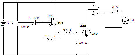
You will notice that rotation must be above a certain rate or the Lamp doesn't light. Circuit operation depends on the charging current on the 3.3uF Capacitor. The charging current of the 3.3uF is the only source of base-bias on the 2SA(B) in order to turn it ON. The 2SA(B) is in the base-bias circuit of the 2SA(2) so that the 2SA(2) cannot be turned ON except when the 2SA(B) is ON.
The 2SA(1) turns the Lamp ON by energizing the Relay.
The 10K in the base-emitter circuit of the 2SA(2) helps eliminate leakage current effects and also helps set the rate of Control change to some extent. The 10K and 47K connected to the 2SA(B) are used to limit circuit current in the 2SA(B) C-E and 2SA(2) B-E.
The 22K helps minimize leakage effects from the 2SA(B) and controls the rate of Control change required to turn the Lamp ON.
The 3.3uF Capacitor discharges through the 2.2K, 22K and 10K Resistors when the Control is reduced to minimum (full CCW). About a second or so is required to insure a full discharge before using the accelerometer.

![]()