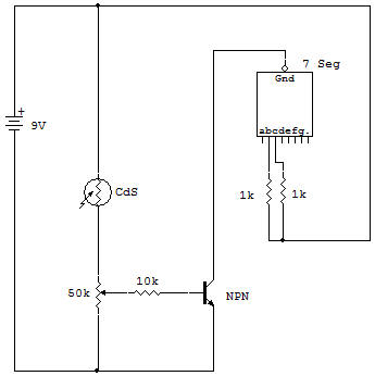
Transistor, CdS Cell and LED Display Circuit

The Qurpose of this project is to learn how a bipolar Transistor and CdS Cell can be used to turn on a readout device. The cadmium sulfide (abbreviated CdS) cell may be thought of as a Resistor which changes its resistance due to a change in light. Its resistance in darkness is very high, usually in the range of 5 megohms, in bright sunlight the resistance decreases to about 100 ohms, or less. Intermediate amounts of light cause intermediate values of Resistance.
You can verify this by setting your VOM to the ohmmeter function and connecting it across the CdS Cell before wiring the Cell into the circuit. Different amounts of light will cause different amounts of resistance.
The bipolar Transistor (an NPN in this case) is used as an active switch. That is, resistance between collector and emitter is so high that it acts like an open circuit until a positive voltage is applied to the base through the 10K limiting resistance. This positive voltage on the base is sufficient to turn ON the Transistor, causing collector-to-emitter resistance to decrease until required current can flow to the LED Display.
The Transistor only drops a few tenths of a volt, when full ON. This very small voltage drop is negligible compared to the 9V applied voltage, so operation is similar to a closed switch. Use your VOM as a voltmeter across the C-E of the Transistor to verify this action.
The amount of voltage across the 50K Control depends on the resistance of the CdS Cell, which depends on the amount of light striking the Cell. Thus, the amount of voltage at the output of the Control depends on both the setting of the adjustable contact inside the Control and the amount of light.
Use your voltmeter across the output of the Control to verify this voltage change. The Control is adjusted to obtain ON-OFF operation over the desired range of light. The seven-segment LED readout is shown wired to display the numeral "1" in the presence of bright light. Obviously it can be wired to display any desired character. At this time we might consider the "1" to be a binary digit, which stands for a logic "high" (H or ON), to indicate the presence of a high level of light on the CdS Cell.
Can you rewire the readout to display another convenient character to indicate this condition?
