
Formulas and Laws Part 1
see also Formulas and Laws Part 2
OHM’S LAW FOR DIRECT CURRENT
All substances offer some resistance to the flow of current. Ohm/’s law states that the current in a closed circuit (Fig. 1) is directly proportional to the applied voltage and inversely proportional to the resistance.

Thus:
I=E/R, E=IR, R = E/I
where,
I is the current in amperes,
E is the voltage in volts,
R is the resistance in ohms.
DC POWER FORMULAS
The power P expended in load resistance R when current I flows under a voltage pressure E can be determined by the formulas:
P = EI, P = I²R, P = E²/R
where,
P is the power expressed in watts,
E is the voltage in volts, Tis the current in amperes,
R is the resistance in ohms.
OHM’S LAW NOMOGRAPH
Using the nomograph in Fig. 2 is a convenient way of solving most Ohm’s law and dc power problems.
Fig. 2

If two values are known, the two unknown values can be determined by placing a straightedge across the two known values and reading the unknown values at the points where the straightedge crosses the appropriate scales. The figures in bold face (on the right side of all scales) cover one range of given values, and the figures in light face (on the left side) cover another range.
For a given problem, all values must be read in either the bold- or light-face figures.
Example
What is the value of a resistor if a 10-volt drop is measured across it and a current of 500 milliamperes (0.5 ampere) is flowing through it?
What is the power dissipated by the resistor?
Answer—The value of the resistor is 20 ohms. The power dissipated in the resistor is 5 watts.
RESISTANCE FORMULAS
The following formulas can be used for calculating the total resistance in a circuit.
Resistors in series (Fig. 3)
Fig. 3
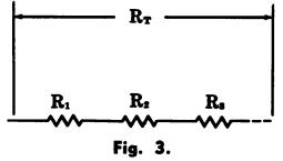
RT =R1+R2+R3 +...
where, RT is the total resistance of the circuit,
R1, R2, and R3 are the resistances of the individual resistors.
Resistors in parallel (Fig. 4)
Fig. 4
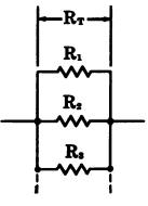

where, RT is the total resistance of the circuit, R1, R2, and R3 are the resistances of the individual resistors.
Two resistors in parallel (Fig. 5)
Fig. 5
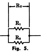

where, RT is the total resistance of the circuit, R1 and R2 are the resistances of the individual resistors.
PARALLEL RESISTANCE NOMOGRAPH
The equivalent value of resistors in parallel can be solved with the nomograph given in Fig. 6. Place a straightedge across the points on scales R, and Rez corresponding to the values of the known resistors.
Fig. 6
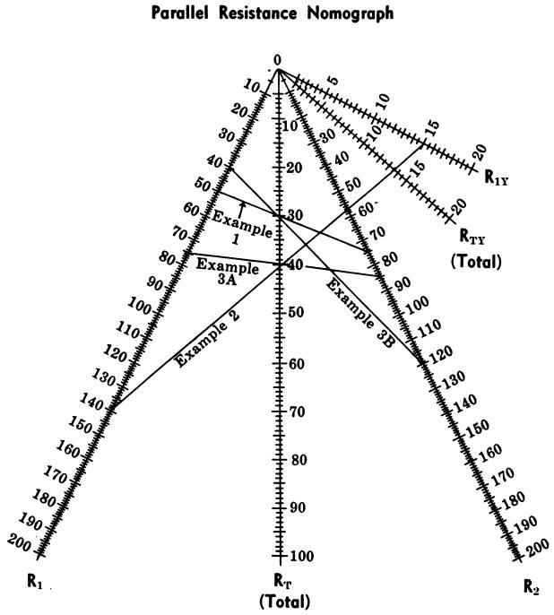
The point at which the straightedge crosses the RT scale will show the equivalent resistance of the two resistors in parallel.
If three resistors are in parallel, first find the equivalent resistance of two of the resistors, then consider this value as being in parallel with the remaining resistor.
If the total resistance is known, the straightedge can be placed at this value on the RT scale and rotated to find the various combinations of values on the R1 and R2, scales which will produce the known total resistance.
Scales R1y and RTy are used with the R, scale when the values of the known resistors differ greatly. The range of the nomograph can be increased by multiplying the values of all scales by 10, 100, 1000, or more, as required.
Example 1
What is the total resistance of a 50-ohm and a 75-ohm resistor in parallel?
Answer—30 ohms.
Example 2—What is the total resistance of a 1500-ohm and a 14,000-ohm resistor in parallel?
Answer—1355 ohms. Use R1 and R1y scales; read answer on RTy scale.
Example 3
What is the total resistance of a 75-ohm, an 85-ohm, and a 120-ohm resistor in parallel?
Answer—30 ohms.
First, consider the 75-ohm and 85-ohm resistors, which will give 40 ohms; then consider this 40 ohms and the 120-ohm resistor, which will give 30 ohms.
KIRCHHOFF’S LAWS
Kirchhoff’s voltage law states: “The sum of the voltage drops around a dc series circuit (Fig. 7) equals the source or applied voltage. In other words, disregarding losses due to the wire resistance:
Fig. 7
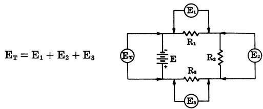
where, ET is the source voltage, E1, E2, and E3; are the voltage drops across the individual resistors.
Kirchhoff’s current law states:
“The current flowing to- ward a point in a circuit must equal the current flowing away from that point.”
Hence, if a circuit is broken up into several parallel paths (Fig. 8), the sum of the currents through the individual paths must equal the current flowing to the point where the circuit branches, or:
Fig. 8

where, IT is the total current flowing through the circuit, I1, I2, and I3 are the currents flowing through the individual branches.
In a series-parallel circuit (Fig. 9) the relationships are as follows:
Fig. 9
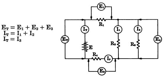
DC METER FORMULAS
The basic instrument for testing current and voltage is the moving-coil meter. The meter can be either a dc milli-ammeter or a dc microammeter.
A series resistor converts the meter to a dc voltmeter, and a parallel resistor converts the meter to a dc ammeter. The resistance of the meter movement is determined first, as follows. Connect a suitable variable resistor R, and a battery as shown in Fig. 10.
Fig. 10
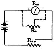
Adjust resistor R, until full-scale deflection is obtained.
Then connect a variable resistor R, in parallel with the meter, and adjust R, until half-scale deflection is obtained.
Disconnect R, and measure its resistance. The measured value is the resistance of the meter movement.
Voltage Multipliers (Fig. 11)

where, R is the multiplier resistance in ohms, Es is the full-scale reading in volts, Is is the full-scale reading in amperes, Rm is the meter resistance in ohms.
Shunt-Type Ohmmeter for Low Resistance (Fig. 12)
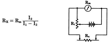
where, Rx is the unknown resistance, Rm is the meter resistance in ohms, I1 is the current reading with probes open, I2 is the current reading with probes connected across unknown resistor, Rm; is a variable resistance for current limiting to keep meter adjusted for full-scale reading with probes open.
Series-Type Ohmmeter for High Resistance (Fig. 13)

where, Rx is the unknown resistance, R1 is a variable resistance adjusted for full-scale reading with probes shorted together, Rm is the meter resistance in ohms, I1 is the current reading with probes shorted, I2 is the current reading with unknown resistor connected.
Ammeter Shunts (Fig. 14)

where, R is the resistance of the shunt, Rm is the meter resistance in ohms, N is the scale multiplication factor, Im is the meter current, Is is the shunt current.
Ammeter With Multirange Shunt (Fig. 15)

where, R, is the intermediate value in ohms, R1 + R2 is the total shunt resistance for lowest full-scale reading, Rm is the meter resistance in ohms, N is the scale multiplication factor.
CAPACITANCE FORMULAS
Total Capacitance The following formulas can be used for calculating the total capacitance in a circuit.
Capacitors in parallel (Fig. 16)
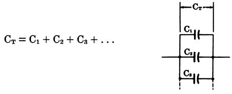
where, CT is the total capacitance in a circuit, C1, C2, and C3 are the values of the individual capacitors. The capacitance of a parallel-plate capacitor is determined by:

where, C is the capacitance in picofarads, K is the dielectric constant, A is the area of one plate in square inches, d is the thickness of the dielectric in inches, N is the number of plates.
Capacitors in series (Fig. 17)

where, CT is the total capacitance in a circuit, C1, C2, and C3 are the values of the individual capacitors.
Two capacitors in series (Fig. 18)

Charge Stored
The charge stored in a capacitor is determined by:
Q = CE
where, Q is the charge, in coulombs, C is the capacitance in farads, E is the voltage impressed across the capacitor.
Energy Stored
The energy stored in a capacitor can be determined by:
W= CE² / 2
where, W is the energy in joules (watt-seconds), C is the capacitance in farads, E is the applied voltage in volts.
Voltage Across Series Capacitors
When an ac voltage is applied across a group of capacitors connected in series (Fig. 19), the voltage drop across the combination is equal to the applied voltage.
The drop across each individual capacitor is inversely proportional to its capacitance. The drop across any capacitor in a group of series capacitors is calculated by the formula:
Fig. 19

where, Ec is the voltage across the individual capacitor in the series (C1, C2, or C3), EA is the applied voltage, CT is the total capacitance of the series combination, C is the capacitance of the individual capacitor under consideration.
NOTE: CT, and C may be in any unit of measurement as long as the unit selected is the same for both.
INDUCTANCE FORMULAS
The following formulas can be used for calculating the total inductance in a circuit.
Inductors in series (with no mutual inductance) (Fig. 20)
Fig. 20

where, LT is the total inductance of the circuit, L1, L2, and L3 are the inductances of the individual coils.
Inductors in parallel (with no mutual inductance) (Fig. 21)
Fig. 21
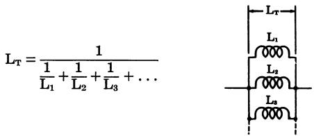
where, LT is the total inductance of the circuit, L1, L2, and L3 are the inductances of the individual coils.
Two inductors in parallel (with no mutual inductance) (Fig. 22)
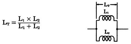
where, LT is the total inductance of the circuit, L1, L2, are the inductances of the individual coils.
Mutual Inductance
The mutual inductance of two coils with fields interacting can be determined by:

where, M is the mutual inductance expressed in the same unit as LA and LB, LA is the total inductance of the two coils with fields aiding, LB is the total inductance of the two coils with fields opposing.
Coupled Inductance
The coupled inductance can be determined by the following formulas.
In parallel, with fields aiding:

In parallel, with fields opposing:

In series, with fields aiding:
LT = L1 + L2 + 2M
In series, with fields opposing:
LT = L1 + L2 - 2M
where, LT is the total inductance, L1; and L2 are the inductances of the individual coils, M is the mutual inductance.
Coupling Coefficient
When two coils are inductively coupled to give transformer action, the coupling coefficient is determined by:

where, K is the coupling coefficient, M is the mutual inductance, L1 and L2 are the inductances of the two coils.
Energy Stored
The energy stored in an inductor can be determined by:

where, W is the energy in joules (watt-seconds), L is the inductance in henrys, I is the current in amperes.
