Memory backup circuit
74HC191
In this project, you are going to make a circuit using an electrolytic capacitor, so that the flip-flop is backed up for a while after power is turned OFF.
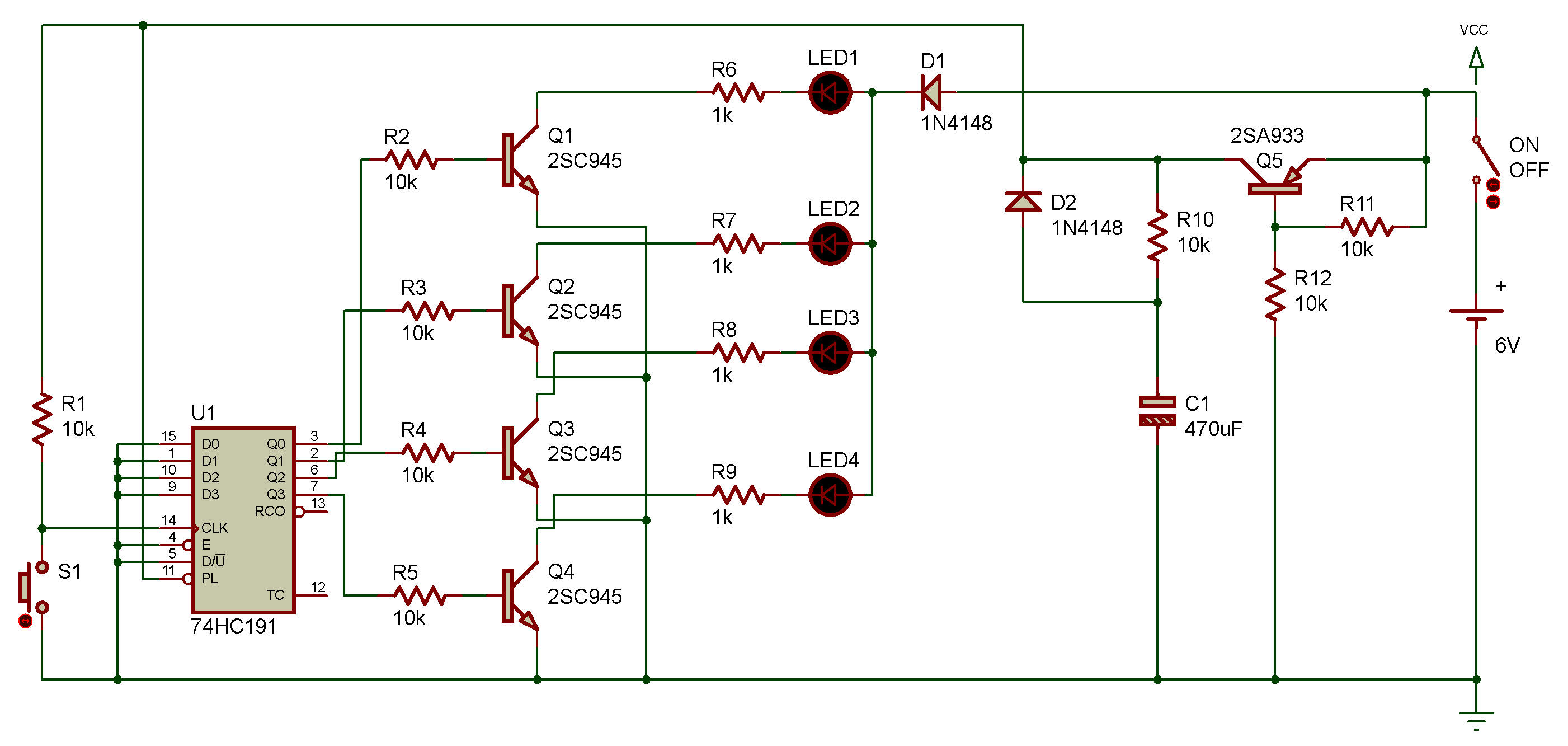
Take a look at the schematic diagram. You'll see the capacitor C1 connected. After power is turned OFF, C1 supplies power to the necessary circuit. You may realize that a capacitor with larger capacitance gives a longer period of backup time. The circuit consists of this C1 and the counter IC, U1. In U1, the flip-flop outputs, Q0 - Q3, are connected to four LEDs.
When you finish wiring, turn power ON and press the key S1. The four LEDs should light at random. Remember the lighting status of the LEDs, then turn power OFF.
After dozens of seconds, turn power ON again. Can you guess how the LEDs will light. As you see, the LEDs light up the same way as they did before power was turned OFF.
Now, turn power OFF and allow the circuit to stand for a few minutes, then turn power ON. Any change this time? Probably, the LEDs should be lighting differently than before.
When power is turned ON, the VCC line receives power through Q5, while C1 is charged through R10. When power is turned OFF, the electricity charged in C1 is discharged through the diode. You may think C1 as a backup battery that works after disconnection of power. Over time, C1 is discharged, however.

![]()