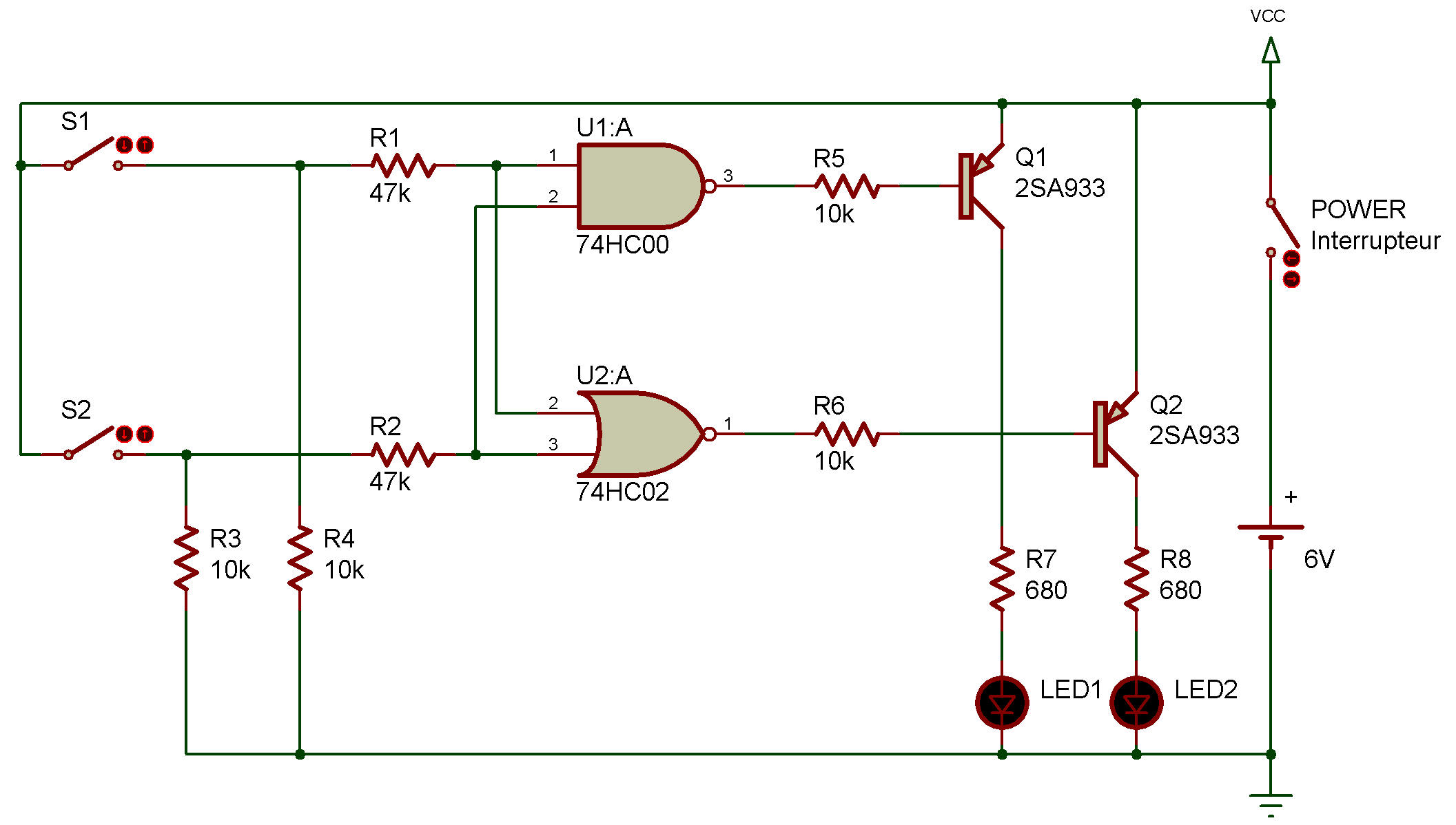
NAND/NOR and transistor switch
74HC00, 74HC02
In this experiment, we're going to find out how NAND and NOR circuits work. Transistors and LEDs are used to indicate the function of these logic circuits.
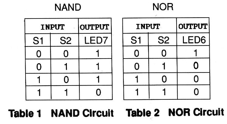
Table 1 shows the NAND circuit function, and Table 2 the NOR circuit function. The input "1" shown in these tables means that keys S1, S2 are ON, and the input "0" means that they are OFF. As for the LED doesn't light up when the output is "1" but does when it is "0". Remember these points.
When you finish wiring up the circuit, switch the power ON.
At this time, S1 and S2 are OFF (input is 0). This means the output of both the NAND circuit and NOR circuit is 1. So, neither LED lights up. Now, see what happens when you press S1.
From the tables, you'll see that the output of the NAND circuit is 0 only when the two inputs are 1, and that of the NOR circuit is 1 only when the two inputs are 0.

![]()