Zener voltage checker II
In Project Zener voltage checker, you've learned a simple zener voltage checker. In this project, you are going to measure zener voltage more accurately using a single transistor.
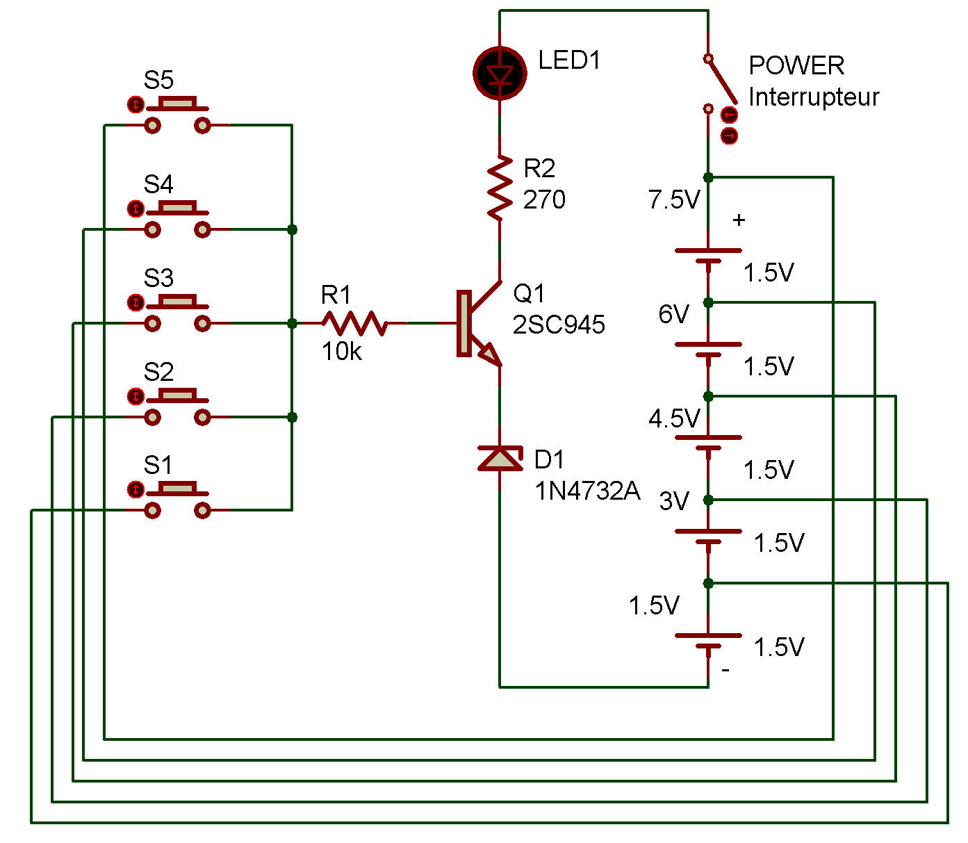
Take a look the schematic. A zener diode is connected to the emitter of Q1. Now, can you guess what value of voltage is required across R1—the resistor connected to the base of Q1—to turn Q1 ON and light LED 1 ?
Yes, the answer is "a voltage greater than the zener voltage of D1." (More precisely, it is a voltage greater than the sum of zener voltage of D1, VBE of Q1, and voltage drop across R1.) If you wish to review the topic of zener voltage, return to Basic operation of zener diode.
When you finish wiring, turn power ON. The keys S1 -S5 should be left OFF. Turn the keys one by one, starting with S1, and see how LED 1 lights. (You should not press two keys simultaneously.) Did LED 1 change as follows?
S1 ON (1.5 V applied): Out
S2 ON (3.0 V applied): Out
S3 ON (4.5 V
applied): Lit dim
S4 ON (6.0 V applied): Lit
S5 ON (7.5 V applied): Lit
bright
From these results, you realize that the zener voltage of D1 is approximately 4.5 V.

![]()