Astable multivibrator
An astable multivibrator is an oscillator that generates a square wave output.
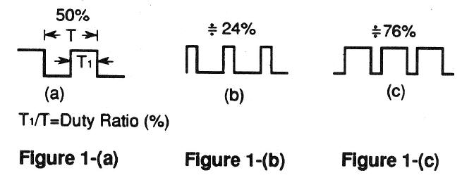
The duty ratio is the ratio of on time (T1) against the one entire cycle of the wave (T). See Figure 1.
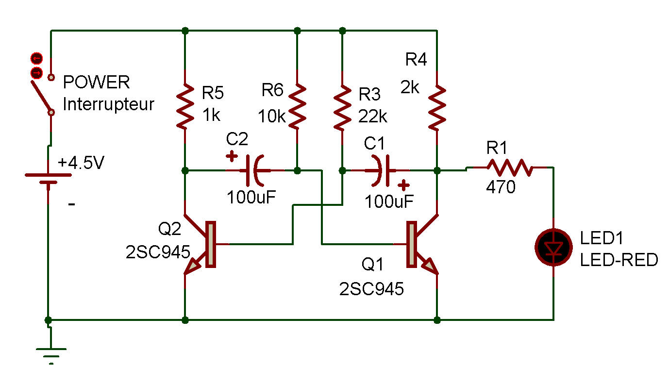
RTL multivibrator
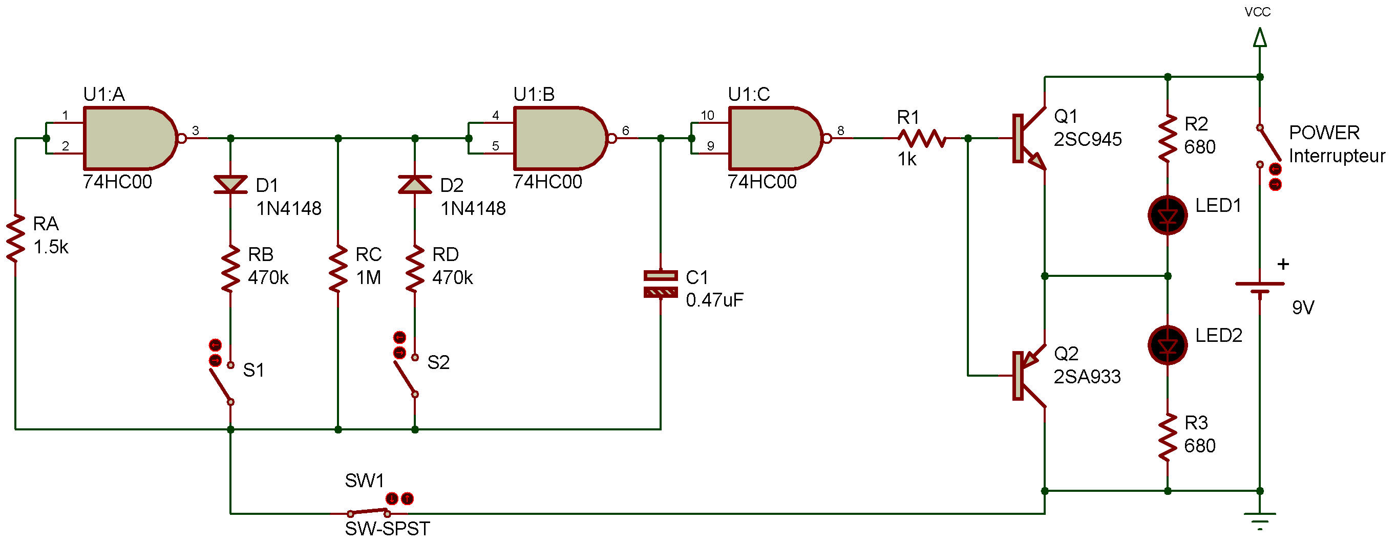
TTL multivibrator
In this project, we're going to experiment with a way of changing the duty ratio of the waveform.
See the schematic:
the astable multivibrator we're going to make uses a NAND gate. The frequency of this oscillator circuit is determined by C1 and RC.
When you press S1 or S2, the duty ratio changes. We can see this change by watching LEDs. Transistors Q1 and Q2 are for switching LEDs on and off.
When you finish wiring up the circuit, turn power ON and see what happens to the LEDs:
they take turns lighting at regular intervals. The circuit must be in the state shown in Figure 1 -(a).
Now press S1, and you'll notice that LED 2 stays on for a shorter period, corresponding to the state shown in Figure 1-(b).
Now release S1 and press S2, and you'll see LED 2 stays on for a longer period this time, corresponding to the state shown in Figure 1-(c).
Now you understand what this project is telling us ....we can change the duty ratio freely with an astable multivibrator.

![]()