
Gunner oscillator pulse
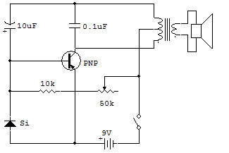
This project is a pulse oscillator that mimics the sound of a machine gun or a motorcycle engine with a cylinder. The 50K control setting allows you to get a few pulses per second or a dozen more.
The basic oscillator circuit is exactly the same as Pulse Oscillator Tone Generator project in Oscillator section except for the addition of the silicon diode (Si), a change in value of the base capacitor of 0.05 uF and the supply voltage change the 3 to 9 volts.
We also returned to the circuit diagram. An electronics technician has to get used to recognize the basic types of circuits regardless of the position of the diagram.
Consider the reason for including the silicon diode to the project but not the project Pulse Oscillator Tone Generator. Remember that during the pulse generation, the basic capacitor (a 0.1 uF in this circuit) is quickly charged by the cell and induces the top of the transformer a voltage higher than the 9 volt battery.
Without the silicon diode current to be passed to the transistor base is excessive (about 80 mA for this circuit). This would not be a problem for capacitors of low value but high value required for the low-frequency pulses (10 uF here) because so many total current that the transistor could be ruined.
The silicon diode in parallel to the junction B-E of the transistor provides a second path for the current so that the transistor base current is limited to a maximum of about 20 mA (safe value for the pulses generated). The diode does not infer the normal operation because of its conduction characteristics hastened.
It takes about 0.3 volts of voltage to a silicon diode before the current flow is initiated, but once the current flow is initiated, the current can be greatly increased without the voltage at the diode increases for worth it.
Junction B-E of the transistor, meanwhile, starts to conduct at about 0.1 volts, but increases in voltage faster than the silicon diode does. The result is that by the time the maximum current of the junction B-E of the transistor passes, the silicon diode started driving. The excessive current pass by the diode which has the possibility without suffering damage.
To experiment, try different capacitor values instead of 10 uF. Make sure you observe the correct polarity capacitors marked with a sign (+).
![]()