
Light Receiver or Light Alarm
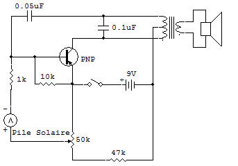
This project makes use of the Solar Cell to control the operation of an audio oscillator. The audible output may then be used as an alarm to indicate the presence of light. This could be used to get you up in the morning at the crack of dawn. It could also be used as an alarm where the presence of excessive light is undesirable, such as in a photo lab.
The circuit is adjusted by setting the 50K Control to the point just below that which will start low level oscillations. Then as the light level is increased the Solar Cell develops sufficient additional voltage to start the circuit into oscillation.
You will want to experiment with the Control setting as it is the key to obtaining the turn ON characteristics you want. The oscillator circuit is the common pulse type, which we've described elsewhere so we won't repeat it here see Oscillator Section.
However, the control circuitry is unique, so we will describe it. With light not applied to the Solar Cell, the Transistor base-bias voltage is obtained entirely from the voltage divider (made up of the 47K Resistor and 50K Control). This voltage is further divided by the Solar Cell resistance, the 22K and the 10K.
The Control can be adjusted to obtain from zero volts bias to above the 0.6 volts or so needed to begin oscillations. Normal Control settings should be for a base voltage to the Transistor, which is slightly below that required to start oscillations.
Now as light hits the Solar Cell it generates additional voltage in the circuit to overcome the difference between that from the 50K Control and that required for oscillator operation.
![]()