
Low Distortion Sine wave Oscillator
The purpose of this project is to build and study a low-distortion sinewave oscillator. This project should be built and used after you have built and studied project Sine wave Audio Oscillator in Oscillator section.
This oscillator is better than project Sine wave Audio Oscillator because there is no Transformer, with its inherent nonlinear characteristics, to cause distortion. The adjustment for low distortion is similar in that you listen to the tone and adjust the Control for the clearest-sounding single tone. Start with the Control near maximum.
The frequency of operation is about 300 hertz, at the minimum distortion setting of the Control. If oscillations cannot be made to continue, the 3V and 9V Batteries can be connected in series to obtain the higher required gain, and therefore sustain oscillations.
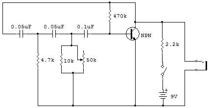
This circuit is a popular basic oscillator known as an "RC phase shift" oscillator. You will find this circuit described in many theory texts. Oscillations occur at the one frequency where the RC circuit values cause a 180 degree phase shift in voltage. The 180 degree phase shift is required to obtain regenerative feedback for a common-emitter stage such as this.
A voltage at the base appears at the collector, amplified and out of phase with the output voltage by 180 degrees. Therefore, to feed this voltage back into the input in the same phase as the original input voltage (regenerative phase) a phase shift of 180 degrees is required.
The RC (Resistor-Capacitor) network composed of the three Capacitors, the 4.7K, 10K and 50K Control, and the B-E input resistances of the Transistor causes exactly 180 degrees of phase change at only one frequency. This is the frequency of sinewave oscillation. An RC network can shift the phase of a voltage due to the action of the Capacitor on the current that flows in the circuit.
A Capacitor operating alone can cause the current to be 90 degrees leading the voltage. That is, the current maximum (and minimum) occurs 90 degrees ahead of the voltage maximum (and minimum). Any resistance in the circuit causes the phase difference to be less than 90 degrees.
With a certain resistance the phase shift can be set to 60 degrees, exactly. Then if three of these RC networks are connected in series we can obtain 60 + 60 + 60 = 180 and (presto!) the proper phase shift to produce oscillation. This circuit is easy on batteries (it only draws 2mA) but must not be loaded much or oscillations cannot be sustained. The crystal Earphone does not present much loading to the circuit, so it is ideal.
![]()