Basic machining operations
Introduction
Regardless of the method by which machine parts are made, certain machining operations are fundamental and basic to all manufacturing processes.
For example, holes, slots, screw threads, and other machining operations are frequently performed on parts which may be cut to shape from solid stock; molded to shape by casting; forced into shape by pressing or bending; or fabricated into shape by welding, riveting, or fastening with threaded fasteners.
Drilling
Drilling is a basic machine shop technique dating back to primitive man. It is perhaps the oldest known shop operation.
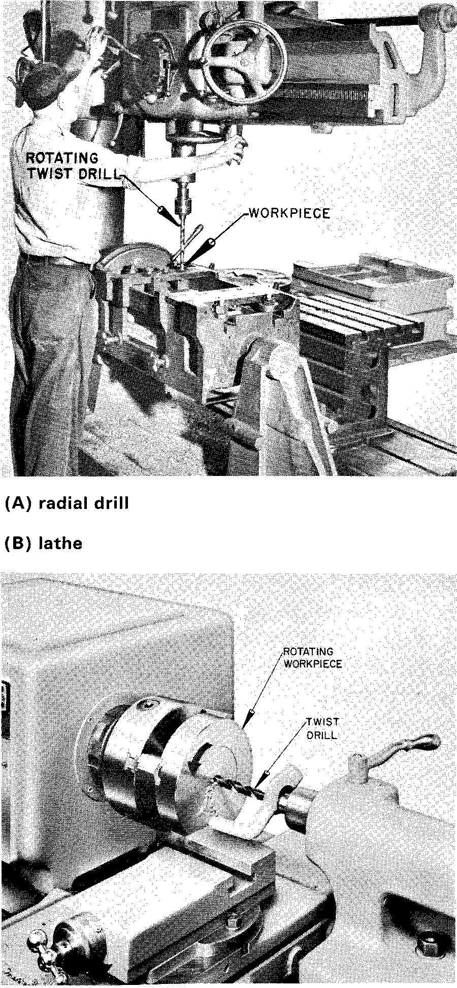
For centuries man has successfully drilled round holes in stone, bone, wood, and metals. As it is done today, drilling consists of cutting a round hole by means of a rotating tool called a drill, Fig. 12-1. The drill is firmly held, either in a device called a drill chuck or in a spindle, and is caused to rotate.
Fig. 12-1. Drilling a hole

As shown in Fig. 12-2, the twist drill (the tool used for drilling) is a round bar of metal which has two spiral grooves, or flutes. (In special cases there may be 3 or 4 flutes.)
Fig. 12-2. Twist drills
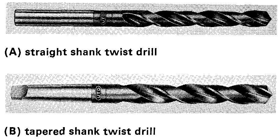
The flutes have a shape which forms suitable cutting lips on the cone-shaped end. They provide channels for the free escape of metal chips.
They also permit lubricating oil to flow down to the cutting edges when the drill is working in a hole. All things considered, the drill is the most efficient tool used by shopmen.
An actual measurement of the cross section of the drill discloses that practically 50 percent of the original metal is removed from a rod in forming the flutes of a drill.
Yet a twist drill will bear more stress in proportion to its own strength than any other tool. It can bear this stress because it is supported by the metal upon which it is operating; therefore it is prevented from springing away from the workpiece.
A twist drill has three principal parts: the point, the body, and the shank. The shank is the end of the drill which fits into the socket, spindle, or chuck of the drilling machine.
There are a number of types of shanks, the most common of which are illustrated in Fig. 12-2. The point is the cone-shaped surface at the other end of the drill.
There are three categories of drill sizes. Each category designates a range of drill diameters as follows: Numerical
Designation:
Numbers 80 — 1 (0.0135 inch to 0.2280 inch)
Alphabetical Designation:
Letters A — Z (0.234 inch to 0.413 inch)
Fractional Designation:
1/64 inch to 3-1/2 inch.
A chart showing all sizes of drills in the numerical and alphabetical designations will be found in Table 12. Drills in the fractional designations increase by 1/64 inch from the 1/64-inch drill through the 3-1/2-inch drill.
Representing a drilled hole
As shown in Fig. 12-3A, the lips of the common twist drill, designed for use on most metals, are ground to an included angle of 118° (or 59° on a side).
Fig. 12-3. Representing a drilled hole
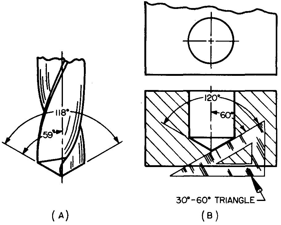
On a drawing the draftsman represents the bottom of a drilled hole to an approximate angle by using a 30°-60° triangle. Thus the drill point is drawn at 60° to the vertical axis.
This is considered close enough for drawing purposes. Figure 12-3B shows how the draftsman uses his 30°-60° triangle to represent the outline of the drill point left in a drilled hole.
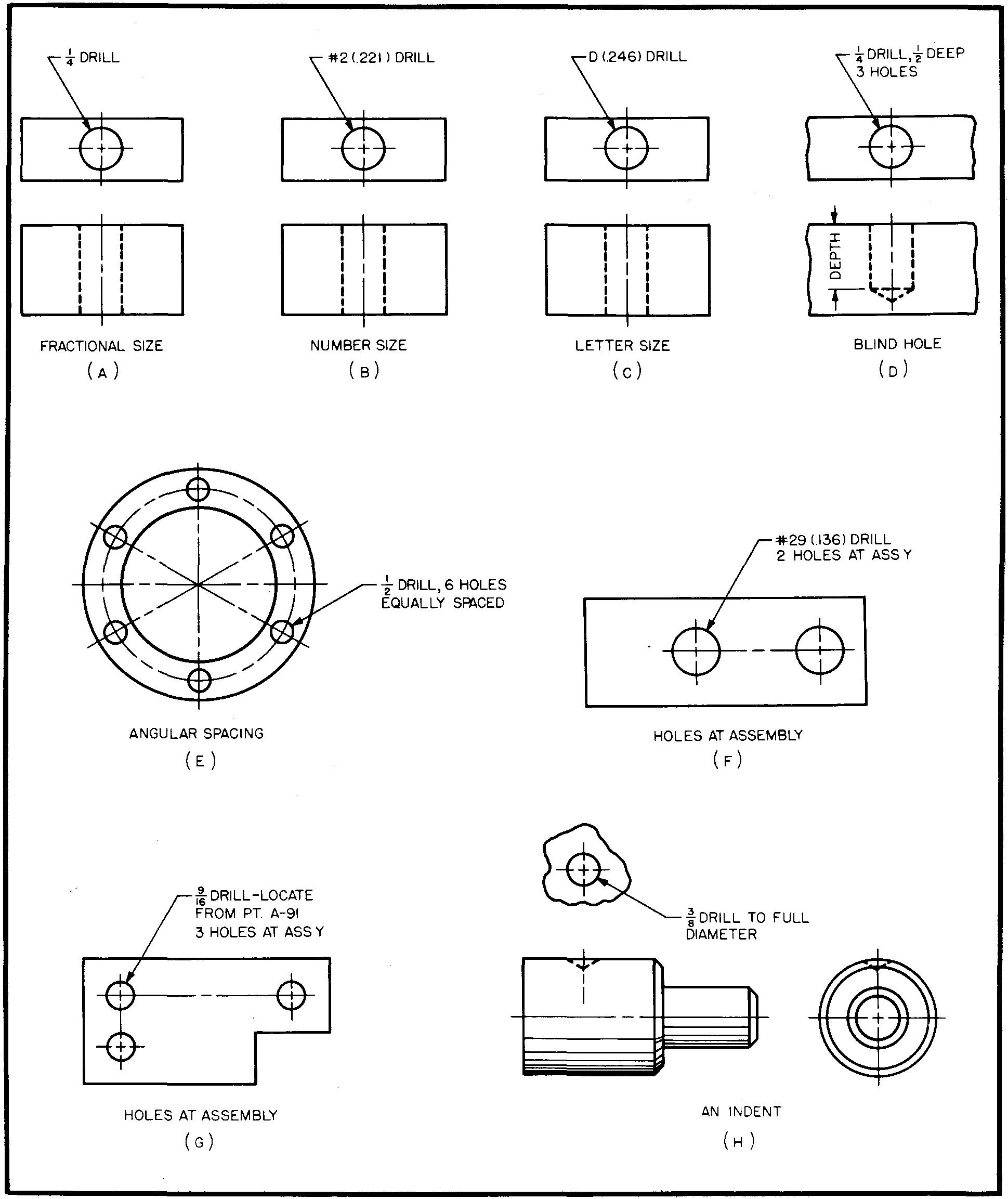
Drilled holes are specified on a drawing as in Fig. 12-4.
Figures 12-4A through C illustrate the various ways to specify through drilled holes. The decimal equivalent of the drill size is given in parenthesis when the number or letter size is given, as in Fig. 12-4 B and C.
The method for specifying the size and depth of a blind drilled hole (or a hole which does not extend entirely through a part) is shown in Fig. 12-4D.
The depth of the hole is always measured to the full diameter of the drill. Other common examples of drilled hole specifications are shown in Fig. 12-4 E through H.
Fig. 12-4. Specification of drilled holes
Boring
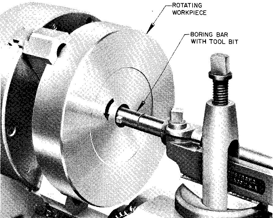
The process of enlarging, straightening, and finishing a hole which has been previously made by drilling or by coring is called boring. (Coring is a method of forming a hole by casting.)
The hole is sized, or enlarged to a definite size, by a tool bit which is held rigidly in a boring bar. Boring is performed by means of a rotating, offset, single point tool called a tool bit. On some boring machines the tool bit stays in place and the work revolves.
On others the reverse is true. A boring operation is shown in Fig. 12-5.
Fig. 12-5. A boring bar with an inserted tool bit
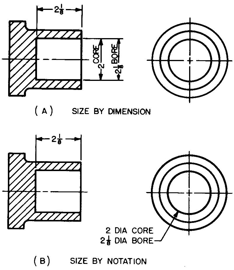
As shown in Fig. 12-6, bored holes may have a square, or flat, end. Machines used to produce bored holes include boring mills, lathes, drill presses, and milling machines.
Bored holes are specified on drawings as shown in Fig. 12-6. As both examples illustrate, the size of the hole which is required before the boring operation is also specified.
Fig. 12-6. Specification of bored holes
Punching
The process of pressing circular and non-circular holes from metal plates and sheets is called punching. Holes are often punched in structural shapes such as angle irons, I beams, and channels. The tool used to form the shape of the hole is called a punch. It is used with a hardened steel plate called a die.
The die is a piece of metal in which there is a hole the same shape as the hole which is to be punched in the workpiece. The hole in the die is slightly larger than the desired punched hole is to be, to allow the punch to enter the hole freely.
The workpiece is placed between the punch and the die. As pressure is applied to the punch, it is forced through the work-piece and into the die. The metal blank, or slug, has thus been forced from the part and pushed through the die.
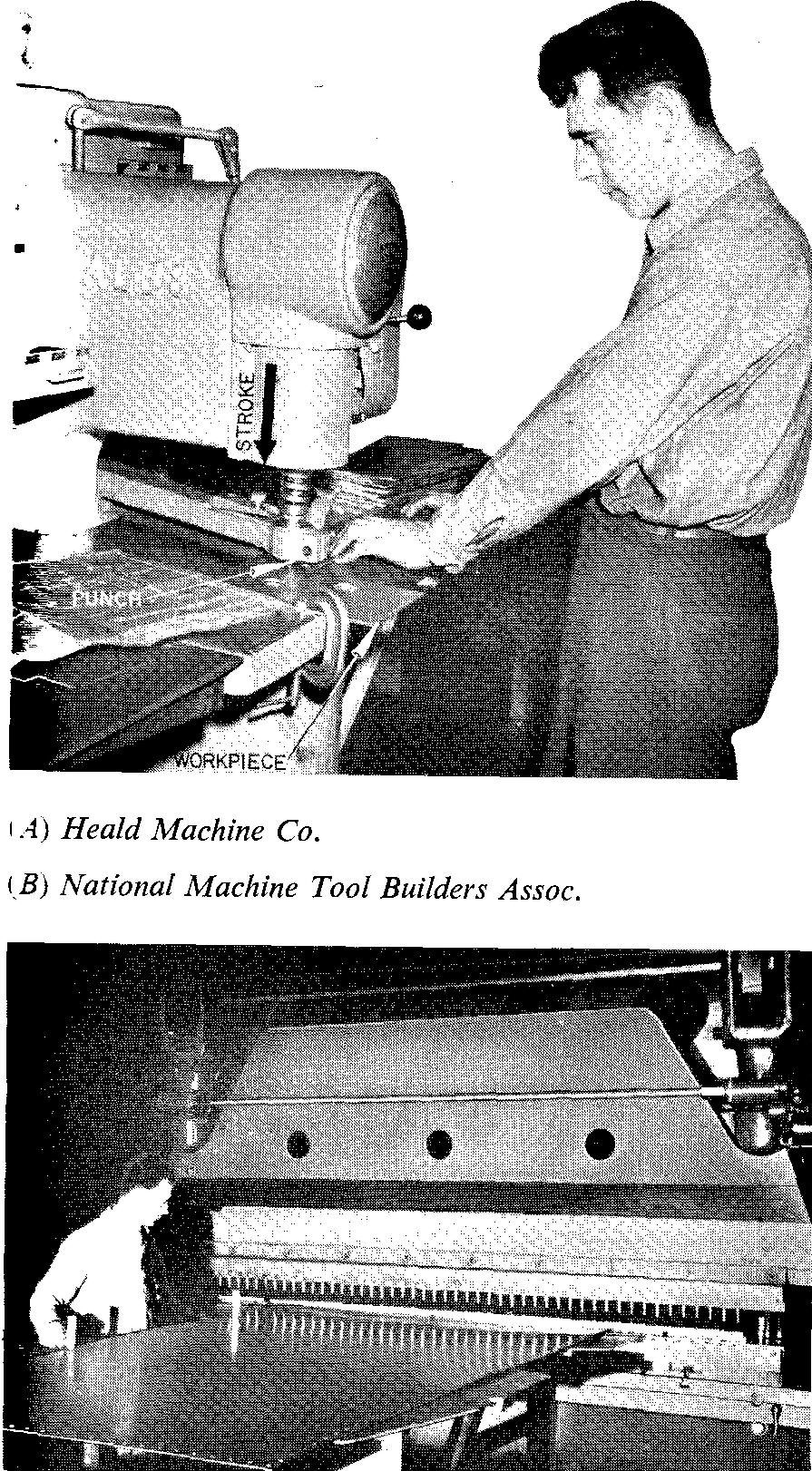
Punching machines vary from small hand-operated types (see Problem 17-22) to large power-driven machines commonly used in boiler shops and shipyards, as shown in Fig. 12-7.
Fig. 12-7. Punching machines
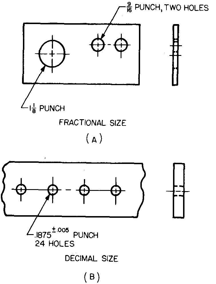
Punched holes may be specified on drawings with either fractional or decimal sizes, as shown in Fig. 12-8. Standard practice in many companies is to include the word punch in the note.
Fig. 12-8. Specification of punched holes
Countersinking
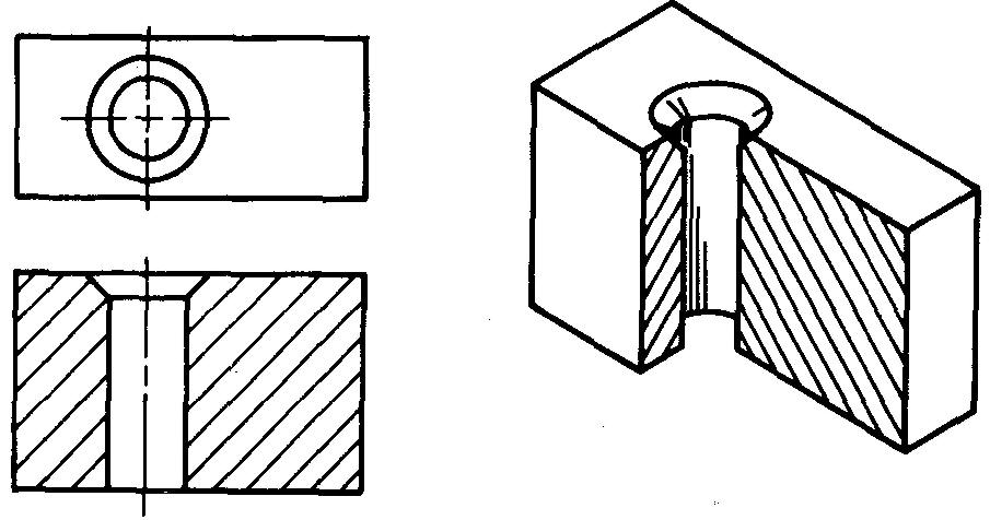
A circular cut made at an angle
to the end of a drilled or bored hole, as shown in Fig. 12-9, is made by
countersinking.
The tool called a countersink consists of a cone-shaped point
with cutting edges.
Fig. 12-9. Countersinking
The shank of the tool is held in a machine which drives the countersink. The point may have an angle from 60° to 85° or an angle of 110° depending upon the requirements of the hole. Two types of countersinks are shown in Fig. 12-10.
Fig. 12-10. Types of countersinking tools
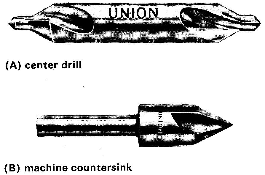
The combined drill and countersink, or center drill, Fig. 12-10A, is used to produce a hole for centering workpieces for the operations of turning and grinding.
A machine countersink, Fig. 12-10B, is used mostly for countersinking holes for screwheads and rivets. Countersinking is performed on drill presses, lathes, and milling machines.
There are two main reasons for countersinking.
1. Countersinking forms a depression or a seat so the top of the conical head of a flat-head screw, bolt, or rivet will be flush with the top of the surface, as in Fig. 12-11.
Fig. 12-11. Countersinking for screws and rivets
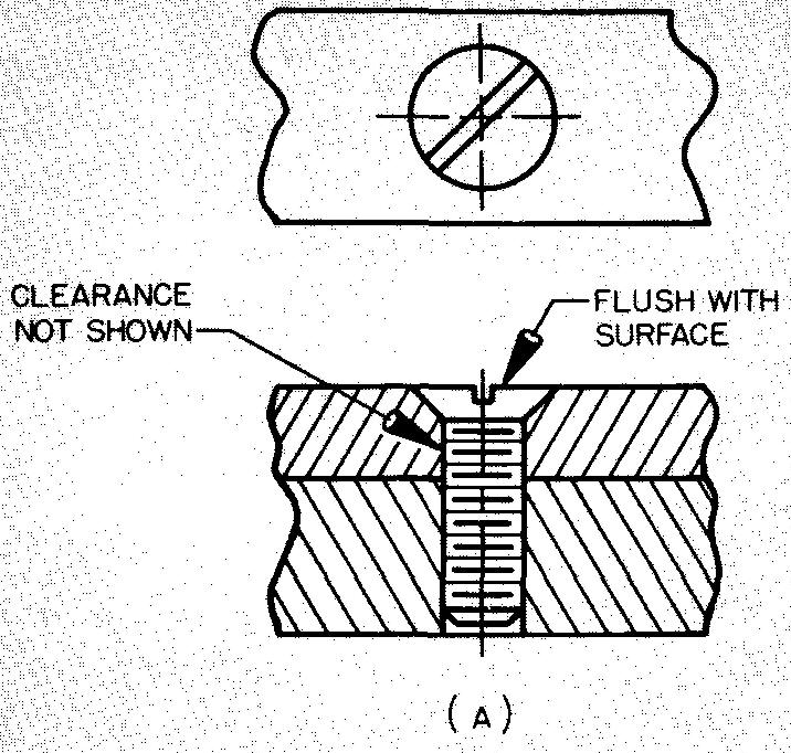
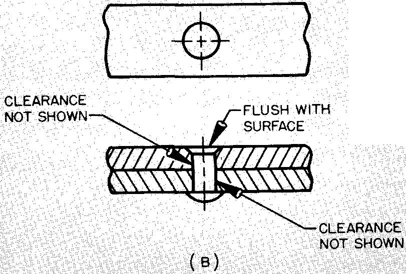
First, a hole is drilled. The drill size (diameter) is generally 1/32 inch larger than the screw size (diameter) or 1/16 inch larger than the diameter of the rivet.
The drilling operation is frequently called clearance drilling. The enlarged hole permits free entry and removal of the bolt and allows the screw to turn freely in the hole. For purposes of simplicity, the draftsman does not draw the clearance when showing the screw installed in position.
The head angle for various screws and rivets varies. The draftsman should check the size of the angle carefully before composing the note which specifies the countersinking operation.
Information as to the sizes of the angles for screws and bolts is given in Tables 15, 17, 20, and 21.
Tables 43 and 44 give the angle sizes for rivets.
2. Countersinking also forms a depression which permits the shoulder of a shaft to fit flat against its mating part, as shown in Fig. 12-12.
Fig. 12-12. Countersinking for radius clearance
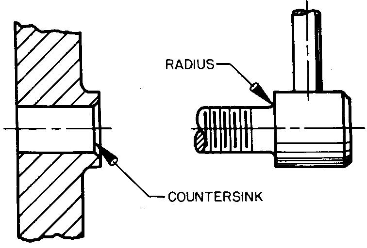
There is usually a small radius left by the cutting tool at the corner of the shoulder and the shaft. The countersinking operation on the mating hole will provide the necessary clearance for this radius.
When countersinking is done on a lathe, by a lathe tool bit, the countersunk hole is commonly referred to as a chamfer.
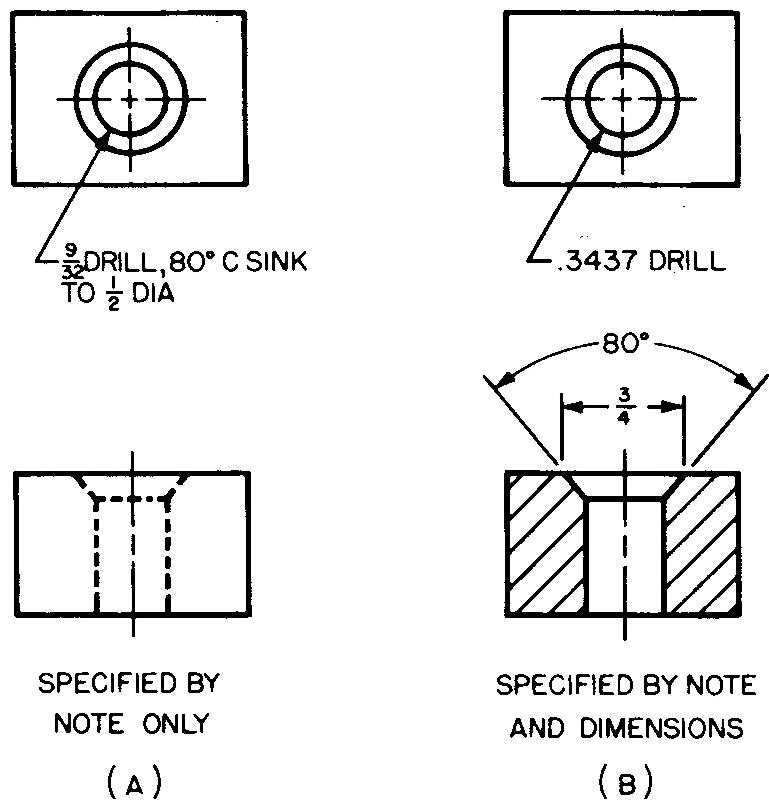
Two methods for specifying countersunk holes are shown in Fig. 12-13. As in the case of drilled holes, the draftsman is not required to accurately represent a countersunk hole.
Thus the draftsman may use a 30°-60° triangle to draw a countersunk hole for a screw-head which has a 62° angle.
Fig. 12-13. Specifying countersunk holes
Counterboring
Making a cylindrical cut on the end of a hole to produce a flat shoulder to a given depth, as shown in Fig. 12-14, is called counterboring.
Fig. 12-14. Counterboring
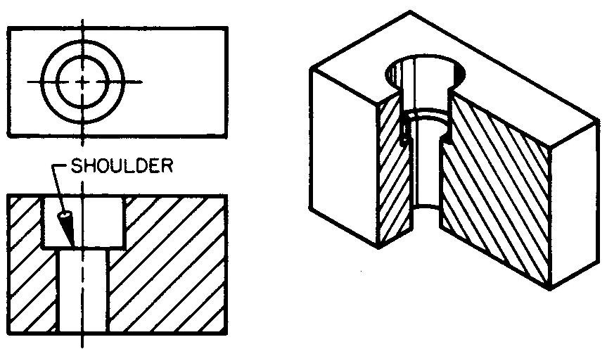
The tool consists of three principal parts: the pilot (not illustrated) and the body and a straight or a tapered shank, shown in Fig. 12-15. The body has cutting edges which cut the hole to size.
Fig. 12-15. Types of counterbores (Union Twist Drill)
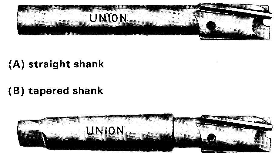
The pilot accurately fits a hole which has been drilled previously. The pilot guides the counterbore with the result that the new hole is centered on, or spaced equally around the drilled hole. Holes such as these are said to be concentric.
The shank is held in the machine which drives the counter-bore. Counterboring is done on a lathe, drill press, or a milling machine. There are several types of counterbores.
There are three main reasons for counterboring.
1. A counterbore forms a depression or seat so that the top of the head of a socket-head cap screw or fillister-head screw will be flush with the top of the work surface, as shown in Fig. 12-16. (In some cases the heads are occasionally set slightly above the work surface.)
Fig. 12-16. Counterboring for socket-head cap screws
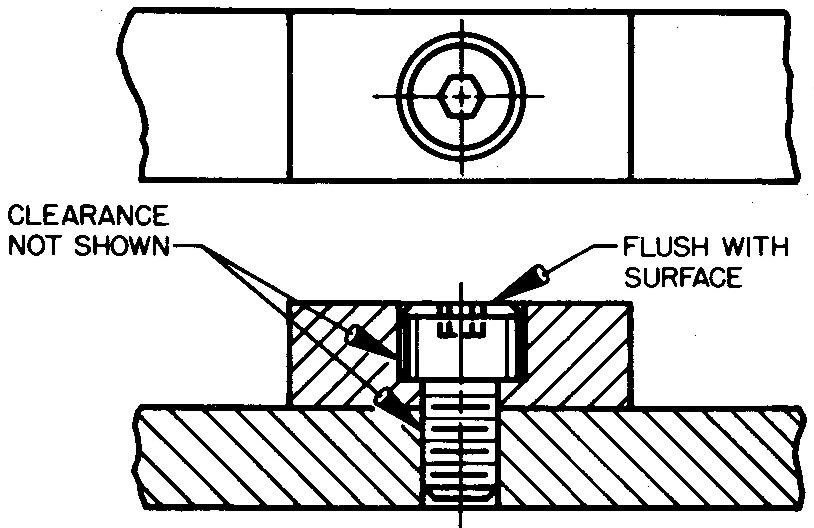
As in the case of countersinking, a clearance hole is drilled prior to counterboring. Although clearance between the hole and the body of the screw is necessary, the draftsman does not show the clearance when the screw is drawn in the hole.
The depth of the counterbored hole is equal to the height of the head of the screw. Table 14 gives the dimensions for these screws.
2. Some parts are fastened with a hexagonal- or square-head cap screw and nut. In some cases it is required to sink the bolt head, the nut, or both, below the surfaces, as shown in Fig. 12-17.
Fig. 12-17. Counterboring for hexagonal-head cap screws and nuts
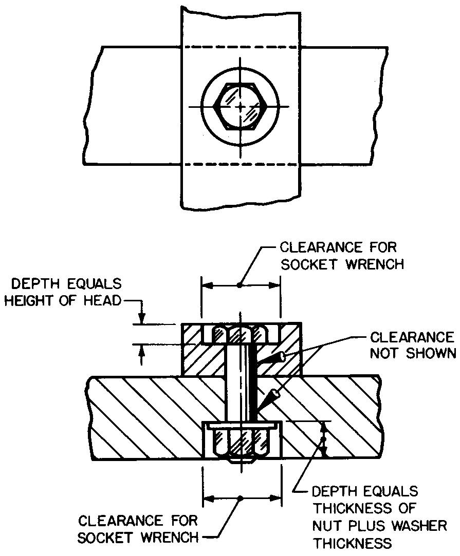
A counterbore sufficiently large enough in diameter must be specified so the socket wrench which is used to tighten or loosen the fastenings will fit in the hole. See Tables 13, 15, and 25 for the dimensions of screws; Tables 31 through 33 for the dimensions of nuts; and Table 37 for the clearance allowances and for the diameters of socket wrenches.
3. Counterboring provides a shoulder or seat for mating parts, as shown in Fig. 12-18.
Fig. 12-18. Counterboring for mating parts
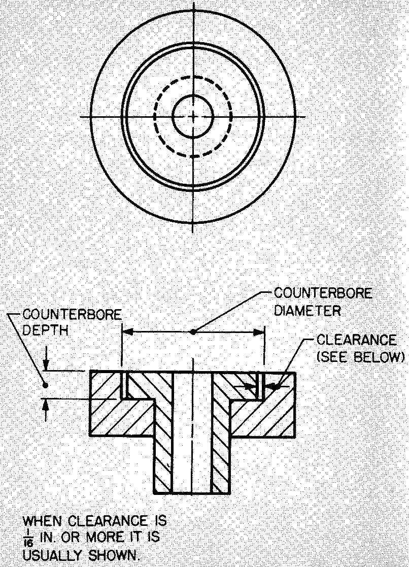
Counterboring for this purpose may be done on a lathe, using a lathe tool bit or a counter-bore tool. In either case, as with screwheads, the diameter and depth of the counterbored hole and any necessary clearance are determined from the size of the mating part.
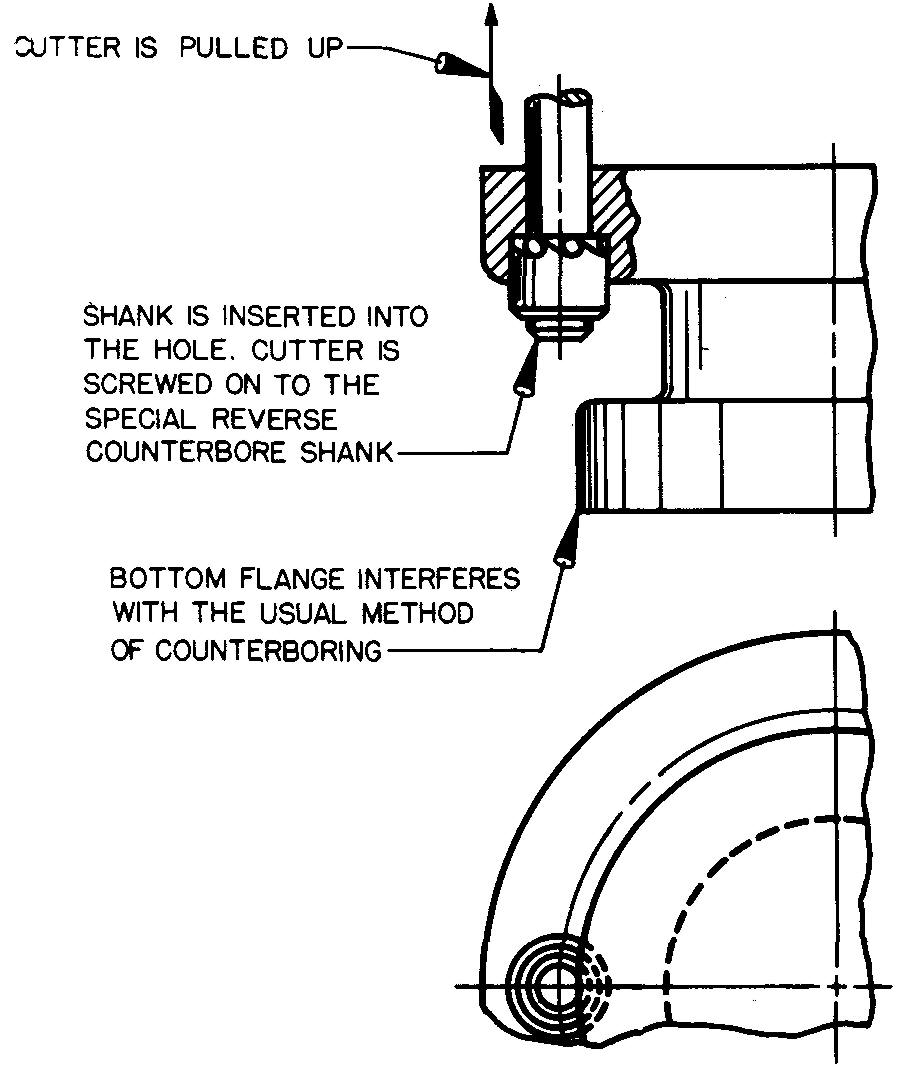
Figure 12-19 shows how a hole is counter-bored when some feature of the part interferes with the usual method of counterboring. The operation is known as reverse counterboring. It is done from the opposite side.
Fig. 12-19. Reverse counterboring
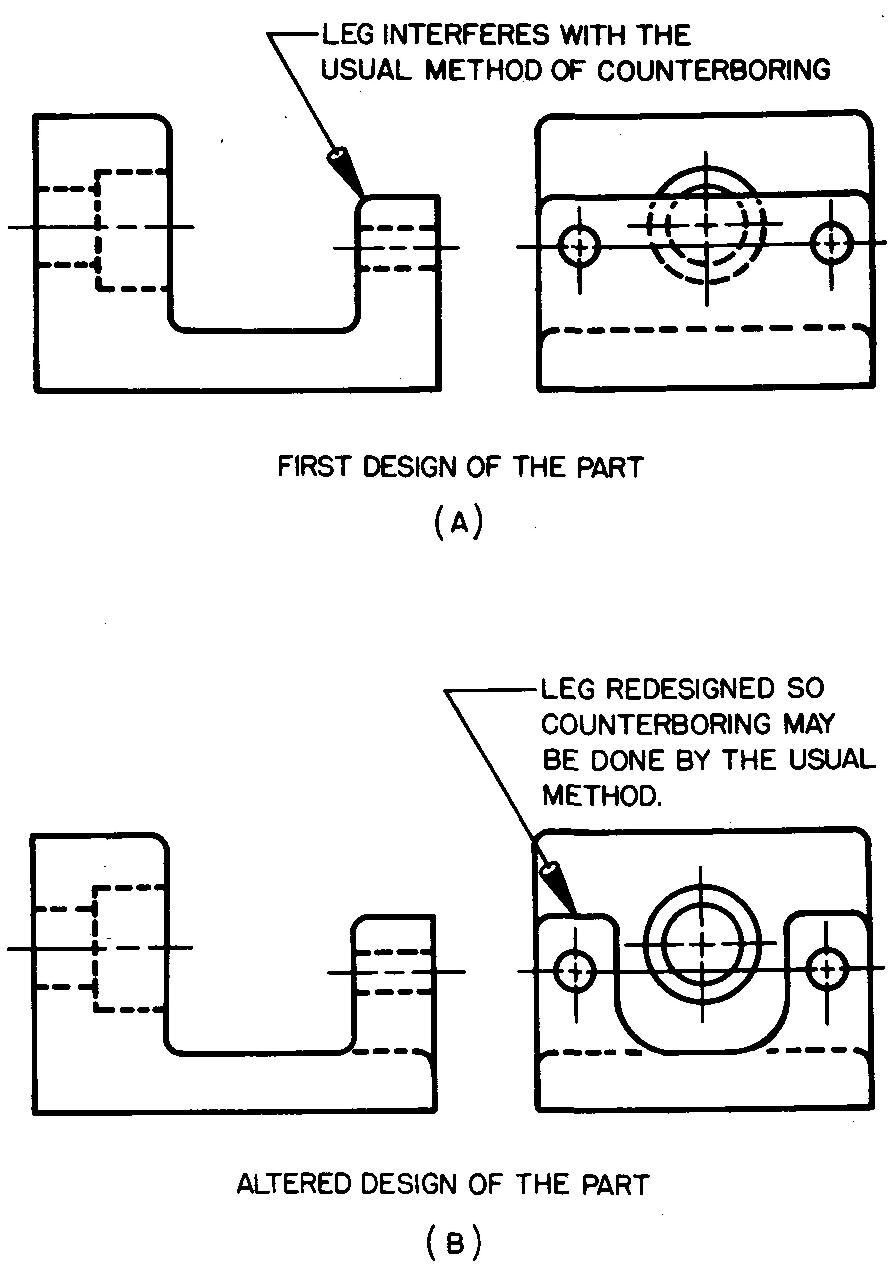
Because this operation takes more time than the usual method and is therefore costly, machine designers and draftsmen try to avoid the need for this operation. Figure 12-20 shows how a design may be altered to avoid reverse counterboring.
Fig. 12-20. An altered design
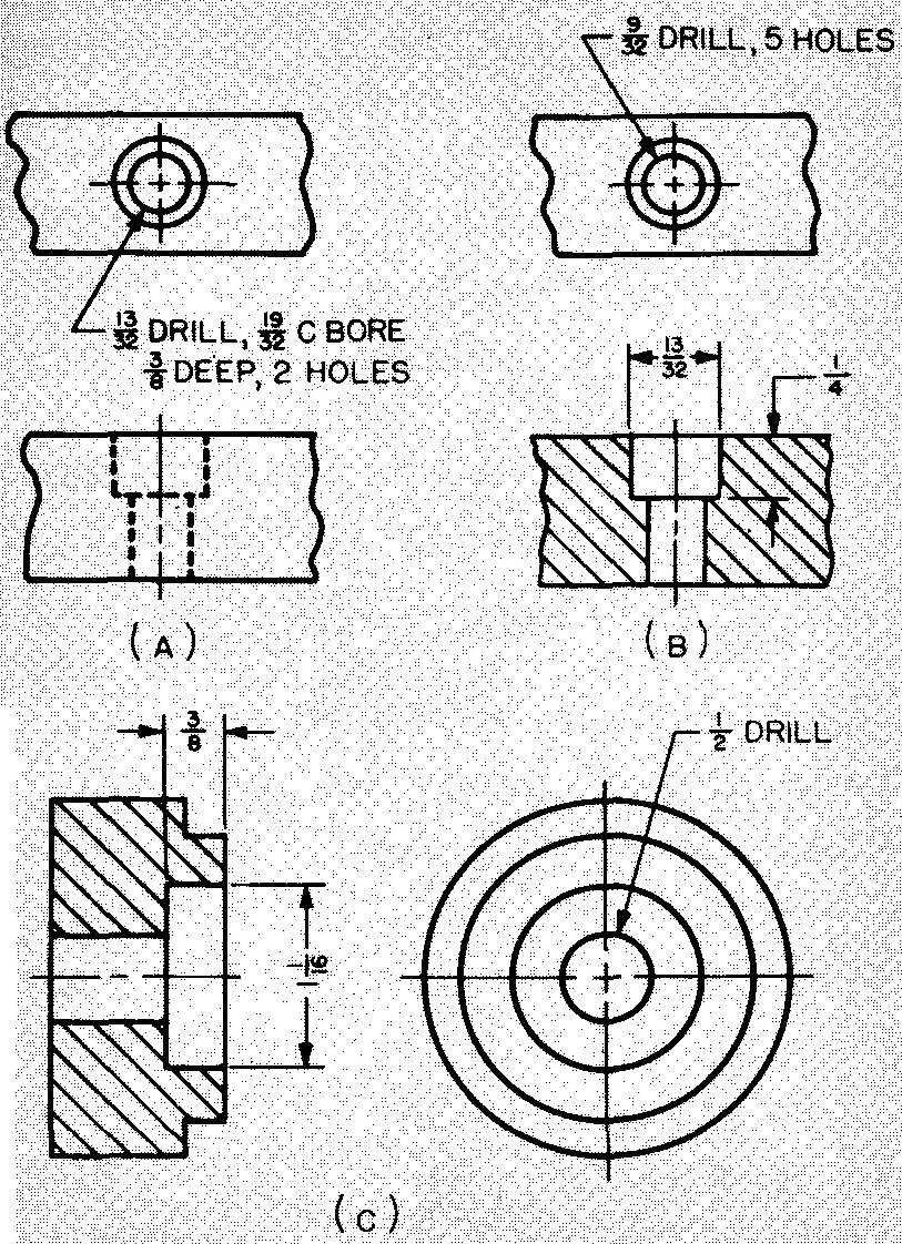
The methods by which the machine draftsman specifies counterbored holes on drawings are shown in Fig. 12-21.
Fig. 12-21. Specifying counterbored holes
Spotfacing
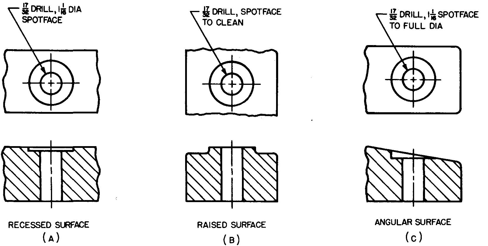
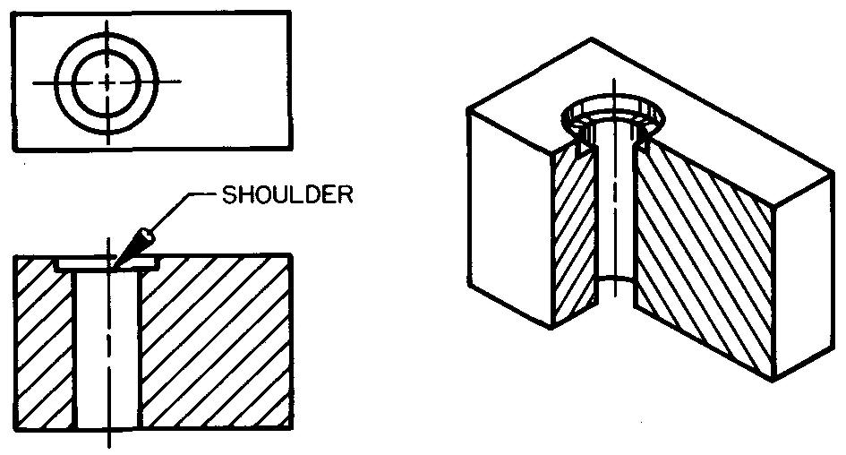
A cylindrical cut to a given depth at the end of a hole for the purpose of finishing a flat seat on a rough surface, Fig. 12-22, is a spotfaced hole. Used this way, spotfacing is the same as counterboring except that the cut is not as deep.
Fig. 12-22. Spotfacing
Spotfacing may also consist of finishing the top of a raised surface such as a boss. (A boss is a circular raised surface.) Either a counterbore tool (Fig. 12-15), a special spotfacing tool, or an end mill (Fig. 13-8K) is used for spotfacing.
There are two main reasons for spotfacing.
1. Spotfacing provides a smooth, flat seat for a bolt head or a nut, as shown in Fig. 12-23.
Fig. 12-23. Spotfacing for bolts and nuts
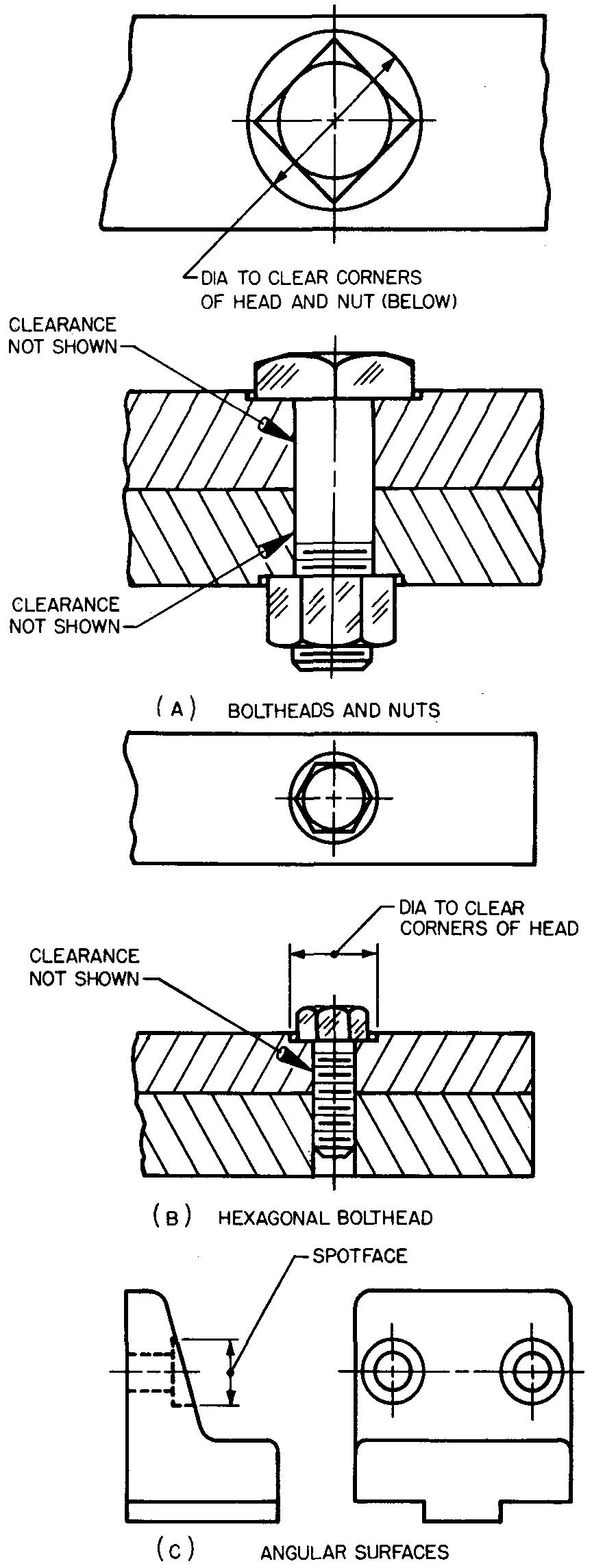
The diameter of the spotface should produce a hole sufficiently large to clear the distance measured across the corners of a hexagonal or square nut or to clear the outside diameter of a washer, if a washer is used.
Dimensions for bolt heads are given in Tables 13, 14, and 15. Tables 31 and 32 list the dimensions for nuts and Tables 34 through 36 list the dimensions for washers.
2. Spotfacing provides a flat seat for a part, such as a handle, on an otherwise rough surface, as shown in Fig. 12-24.
Fig. 12-24. Spotfacing for handles and knobs

Generally the depth of the spotfaced hole is not given in the note on the drawing. According to long standing custom, this depth is left to the judgment of the shopman.
Since the purpose of spotfacing is to smooth off a rough surface, the worker can most accurately judge how deep he must extend the cut into the part.
Figure 12-25 shows examples of how to specify spotfacing operations on drawings.
Fig. 12-25. Specifying spotfaced holes
