Machine Drafting
| Drafting standards for detail drawings | |
|
The American Society of Mechanical Engineers (ASME) is composed of more
than fifty-five thousand members representing every major branch of the
profession in industry, in government, and in education. The general
purpose of the group is to advance the profession of mechanical
engineering. Much important work by the ASME has been done in the development of standards manuals. These manuals consist of a set of carefully written rules and principles on topics pertaining to engineering. The first of such standards began as far back as 1914, when the ASME approved and published the report of its committee on Standards for Cross-Sections. In 1925, the ASME became concerned with the growing need to establish other standards for engineering drawings. Joining with the Society for the Promotion of Engineering Education (now the American Society for Engineering Education), a national committee was formed. Its purpose was to develop additional standards for drawings and drafting room practice. Ten years later, after extensive study, the work of the standardization committees was approved by the American Standards Association (ASA). Since then, changes to the original standards have been made as needed. To keep pace with the growing developments in engineering, many other new standards are constantly being drawn up. We now have drafting manuals covering dimensioning and notes, sheet sizes, sectioning, lettering, projections, screw threads, gears, castings, and forgings, as well as many other topics. All of the standards are based on well established practices. Many companies all over the United States use and follow them. In 1948, the scope of the project was enlarged to include standardization with Great Britain and Canada. The student will note certain references to some of the ASA standards in this text. In addition to the ASA standards, many companies develop additional drafting rules which inform the draftsman of the practices to be followed for his particular company (see Sec. tools and equipment in the industrial drawing room below). In most cases, parts are drawn and dimensioned on the drawing according to the methods by which they are to be made. Parts may be manufactured by using a wide variety of shop processes. Thus, drawing practices may vary slightly within various companies, since no two machine shops have the same equipment for doing the same kinds of work. Special manufacturing requirements often govern the methods by which the shape and size of parts are shown and specified. It is important to learn as many different ways as possible of representing machine parts. The successful machine draftsman must be able to draw individual and assembled machine parts to acceptable standards. Also, he must have a basic understanding of the operating principles and be able to analyze complicated machine designs. If he understands how the moving parts of the various systems operate, the draftsman can prepare drawings which can simplify the job of the shopmen who will manufacture these parts. There are literally hundreds of details the draftsman is required to know. A well informed draftsman can carry out his job with a minimum amount of assistance. |
|
| 1. The industrial drafting room | 2. Technical sketching |
| 3. Principles of detail drawings | 4.Principles of sectional views |
| 5. Conventional representation | 6. Principles of dimensioning |
| 7. Principles of notation | |
| Technical information related to machine drawing | |
|
To be successful in any field, a person should know as much as possible
about his subject. Machine draftsmen find that their subject can be
mastered only with time and effort. After years of work, the goal of a
machine draftsman may still be complete mastery of every item necessary
for a successful performance of his job. There is such a vast amount of important material to be mastered by a machine draftsman that it is nearly impossible for him to retain it all. A careful approach to the field will help the beginning machine draftsman with this problem. It is wise for the beginner to start by patiently learning the established principles and carefully applying them in his drawings, progressing in this manner from simple principles to more complex ones. Through a determined effort to learn these principles and through continued use of them in actual drawing, successful draftsmen have found that they retain much of the technical subject matter. This contains valuable technical information of this type. The problems which occur in the chapters following Part II will require the continued application of the information contained in these four chapters. Work in modern industry requires the draftsman to have additional skills and knowledge well beyond the topics which are covered in the first seven chapters of this text. At this point in your development you should now be acquainted with most of the fundamentals of what a machine draftsman must do to prepare an acceptable drawing. The four chapters in Part II explain some of the important things a machine draftsman must know. For example, the surfaces of a certain metal part cut from steel plate may require no further machining or smoothing. On the other hand, a different part may require a highly polished surface which cannot be produced efficiently at the steel mill but which may result from later machining or stock removal operations. Draftsmen should be able to apply correctly the appropriate surface symbols when necessary and to otherwise indicate the desired surface treatment, depending upon the intended use of the part. There are actually several differently achieved categories of finished surfaces which must be considered. One type of finish refers to the condition of the surface which results from any particular stock removal operation. Included in this, category are surfaces which are produced by milling, knurling, grinding, honing, lapping, and so forth. Surfaces finished in this way are usually identified on the views of the drawing by special finish symbols. Another category (specified either by general or by detail notes) includes those surfaces which are produced for appearance effects only, such as barrel finishing. Finally, there are categories which include special processes of surface conditions such as paint or plating (see Table 6). Many of these conditions of surface treatment are explained in Section 8. The draftsman should also learn as much as possible about engineering materials and their properties so that he can make an intelligent selection of materials for the parts he draws. Section 9 develops this information. In addition, a successful machine draftsman should be able to understand readily the requirements of designers and engineers in order that he may efficiently carry out their wishes. For this, he must learn new terms such as heat-treating, annealing, ductility, malleability, and hardness testing. Many of the text problems assigned in later chapters refer to Section 9. Section 10 presents the tools of analysis needed for problem solving. A drafting problem must first be analyzed both mentally and graphically (using a drawing or a freehand sketch). Analysis helps to show what is given and what is needed, as well as how to use mathematical tools to solve a problem. Analysis requires intelligent, logical thinking; it is considered the most important part of problem solving. In many mathematical problems, the situation is described, the problem is set up, and the solution is worked out just as the machine draftsman would solve it. Definitions and examples have been condensed to make them readily usable. Actual drafting problems are used to show the student the important role mathematics plays in the preparation of machine drawings. Any single chapter topic may be used by itself as a tool in problem solving. For example, it would not be necessary to study an entire course in solid geometry or trigonometry in order to use what is needed to solve a particular type of related drafting problem. Drafting problems which require solutions using mathematical analysis are assigned in later chapters. The student will gradually be exposed to most of the elements of Section 10 as he proceeds through the text problems. The draftsman should become familiar with the various methods of producing machine parts. Parts produced in large quantities require drawings which are accurately and precisely dimensioned. Each of a group of similar manufactured parts must be as nearly identical to all of the others as possible. Section 11 explains and illustrates methods which are used in modern industry to control the sizing of parts by the use of precision dimensioning on drawings. Practically every machine drawing has at least one precision dimension. Here again text problems in later chapters contain practical applications of the principles of tolerancing. |
|
| 8. Surface treatment of metals | 9. Engineering materials and their properties |
| 10. Drafting mathematics Part 1 | 10. Drafting mathematics Part 2 |
| 11. Principles of tolerancing | |
| Manufacturing processes and machine drawing | |
|
Persons in charge of engineering and shop departments have reported that
a successful machine draftsman must acquire the ability to anticipate
what information the shopman must find on the drawing if he is to make
the part. To be sure, this ability to anticipate the shopman's needs
will not be developed immediately. It will require considerable experience and a reasonably complete understanding of what the shopman's needs actually are. Thus, the more the draftsman knows about the shop conditions, the better he is able to communicate graphically with the worker, providing the necessary information on a drawing. There are several important requirements for the various ways in which draftsmen prepare detail drawings and specify the manufacturing process through which the part is developed to its final size and shape. Every specification for a part is based entirely upon shop requirements. The machine draftsman is employed solely for his ability to convey both written information (figures and notes) and graphic information (symbols, dimensions, and lines) to the shopman. Not only must the draftsman describe what the final part will look like, but by the judicious use of marks, symbols, lines, notes, and so on, he must concisely describe all of the operations involved in the manufacture of the part. There are significant differences in the way in which dimensions and notes are applied, depending upon the intended manufacturing process. Most experienced engineers, draftsmen, and shopmen can readily identify the particular manufacturing process which is to be used to make a part by simply examining the elements of the part as they are shown on the drawing. For the beginning machine draftsman it may not be quite so easy to identify these manufacturing processes until he has gained some experience. In Part III, you shall learn about the various methods by which a draftsman communicates on the drawing with the shopman who will make the part. Upon your completion of the next five chapters of this text, the various elements of your drawings will begin to form a consistent pattern. It will become increasingly evident that your drawing has become more than just a series of lines and symbols. Instead, the drawing will take on the form of a legal document which not only shows the size and shape of the part, but also outlines the operations and orders the materials to be used in its manufacture. Section 12 explains the shop operations which are known as secondary manufacturing processes. These processes include methods by which the surfaces of every known kind of metallic and nonmetallic part is cut, shaped, and finished. It will be noted that these operations are used again and again in connection with the various forming processes described in Section 13, 14, 15, and 16. Section 12. Basic machining operations also lists and illustrates a number of common terms used by engineers, draftsmen, and shopmen to describe the various elements of machine parts. Among the terms are chamfers, flats, hubs, shoulders, and so on. Considerable attention is given to shop procedures for secondary manufacturing processes and to the methods of specification on machine drawings. Section 13, 14, 15, and 16 acquaint the student with some of the more important primary manufacturing processes. Here the emphasis is placed upon an explanation of how the shape of different kinds of machine parts are initially formed. Methods of forming machine parts may be roughly and conveniently divided into four different groups: parts formed by machining, parts formed by casting, parts formed by pressing, and parts formed by fabrication methods. Section 13. Forming parts by machining shows the student how parts may be formed to the desired size and shape by machining. The machine tools which accomplish the various cuts perform operations such as drilling and boring, turning, milling, planning, and grinding. Each of these operations make use of hardened cutting tools to shape the piece by chip removal. The processes for forming metal parts may be roughly compared to the processes by which the cabinetmaker forms various parts of wood furniture. Both parts of wood and parts of metal are formed in a similar manner: in each case you start with rough oversize stock and reduce it down to the desired size and shape by successive cutting operations. Section 14. Forming parts by casting explains how parts may be formed by some of the more common casting processes. Particular emphasis is given in this chapter to the special drafting requirements necessary for cast parts. Most of the casting processes require secondary manufacturing operations after the part has initially been formed to the approximate shape. Section 15. Forming parts by pressure discusses the methods by which parts may be formed to shape by pressing or hammering (forging), by compressing metallic and nonmetallic powders in a die (powder metallurgy), and by pressing or stamping parts from metal sheets. In each case, the special drafting considerations are carefully explained. Section 16. Forming parts by fabricating introduces the student to processes by which parts are fabricated. Included are topics such as welding and sheet-metal practices. As we study these forming methods, we must recognize one important fact: regardless of which primary manufacturing process is used to develop the shape, before it is installed the part usually finds its way tc machine tools which remove stock by cutting. |
|
| 12. Basic machining operations Part 1 | 12. Basic machining operations Part 2 |
| 13. Forming parts by machining | 14. Forming parts by casting |
| 14. Forming parts by casting Review questions | |
| 15. Forming parts by pressure | 16. Forming parts by fabricating |
| Drafting standards for assembly drawings | |
|
Up to this point in the text you have been learning to prepare
acceptable detail drawings of individual parts, complete with dimensions
and all other specifications. The final four chapters will provide you
with experience in preparing assembly drawings, which are drawings of
mechanisms or structures made up of several parts. The preparation of assembly drawings requires a great deal of skill and planning. The draftsman must constantly be on the alert to show the parts in the clearest possible way. He is in a position to make a number of important decisions leading to an efficient assembly drawing. There are several reasons why assembly drawings are used in industry. From an engineering standpoint, the drawing serves as a final check as to how well the individual parts fit together. Thus, the drawing shows the relationship of each of the assembled parts. Assembly drawings are also used by purchasing and stock departments. The drawing is carefully analyzed to determine those parts which may be conveniently purchased. It is also used for ordering the necessary kind and amount of stock needed to manufacture the parts in the shop. Assembly drawings are used in the shop as a guide to assembling or installing the various parts in their proper and final position on the machine or structure. A complete assembly drawing is often the only point of reference available to show how the various parts of an object fit together to make up the whole object. As in the case of detail drawings, there are a number of accepted standards which must be followed when preparing assembly drawings. The following three sections explain and illustrate principles involving cam, gear, and piping drawings. |
|
| 17. Principles of assembly drawings | 18. Principles of cam drawings |
| 19. Principles of gear drawings | 20. Principles of piping drawings |
| Machine Drafting | Dessin mécanique |
| Tables | |
| 1. Standard abbreviations | |
| 2. Natural trigonometric functions | 3. Functions of numbers |
| 4. Weights of materials per cubic inch | 5. Machining tolerances |
|
6.
Surface treatment specifications |
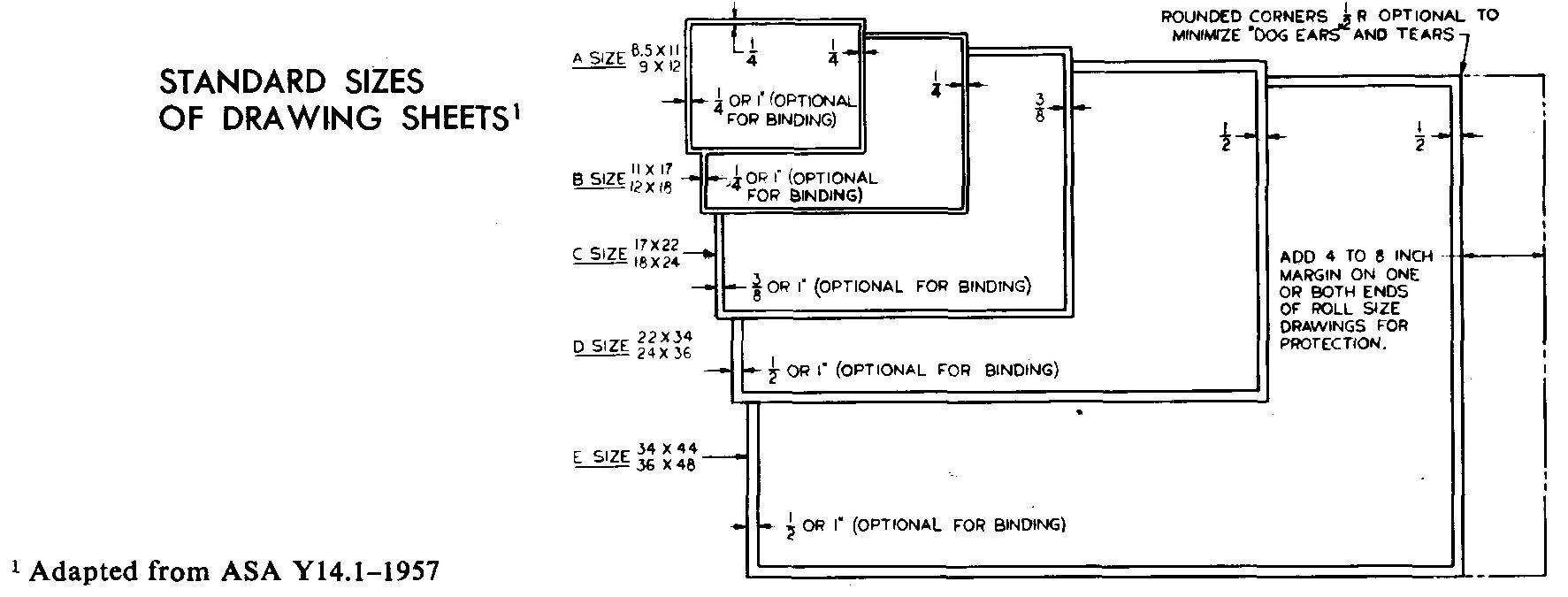
7. Standard sizes of drawing sheets |
|
8.
Unified and american
national screw thread series American standard |
9.
Acme and stub acme threads,
general purpose American standard |
| 10, 11, 12. Identification of various types of screws |
13.
Square and hexagonal bolts and
hexagonal-head cap screws American standard |
|
14.
Cap screws socket and
slotted heads American standard |
15, 16.
Machine screws American standard |
|
17.
Square head set screws American standard |
18.
Set screw points American standard |
| 19. Recommended uses for various styles of set screw points |
20.
Slotted flat head
tapping screws American standard |
|
21.
Slotted oval head
tapping screws American standard |
22, 23, 24.
Slotted round head
tapping screws American standard |
|
25.
Slotted hexagonal head tapping screws
American standard |
26. Thumb screws |
| 27, 28. Torque thumb screws | 29, 30. Bolt length increments |
| 31. Square and hexagon nuts American standard |
32, 33.
Machine-screw and stove-bolt
nuts American standard |
| 34. Plain washers American standard |
35.
Lock washers American standard |
| 36, 37. Tooth type lock washers | 38. Taper pins |
| 40. Straight (dowel) pins | 39. Size and depth when step-drilling taper-pin holes |
| 37. Minimum clearance allowance for wrench movements (through 60°) and socket wrench diameters | |
|
41.
Cotter pins American standard |
42. Tinners rivets |
| 43. Cooper's rivets | 44. Countersunk-head rivets |
| 45. Button-head rivets | 46. Pan-head rivets |
| 47. Truss-head rivets | 49. Gib-head keys, square and flat |
| 48. Stock keys, square and flat, with corresponding shaft diameters | |
| 50. Pratt and whitney keys | 51, 52. Woodruff keys |
| 53. Minimum hub diameters with keyway | 54, 55. Dimensions of morse tapers |
| 56, 57, 58. Dimensions of v belts and sheave grooves | 59. Double arm handles |
| 60, 61. Solid handles and Hand knobs | 62. Ball knobs |
| 63. Handwheels | 64. Gaging systems used for various metals and commodities |
| 65. Wire and sheet metal gages in inch equivalents | 66. Hydraulic grease fittings |
|
67.
Graphic symbols for piping American standard |
68.
Pipe, welded wrought iron American standard |
|
69.
Screwed fittings,
150 lb malleable-iron American standard |
70.
Screwed fittings, cast iron
American standard |
|
71.
Solder-joint fittings,
cast brass American standard |
72. Valves, globe, angle globe and gate |
| 73. Lengths of pipe nipples | 74. Unions, 150 lb. Malleable iron |
|
75.
Flanges and flanged
fittings, cast iron American standard |
76. Elbows, tees, caps, and stub ends |

![]()